
Movement detection system, movement detection device, movement detection method and computer program

A motion detection and motion technology, applied in transmission systems, motion accessories, selection devices, etc., can solve problems such as complicated device structures and increased production costs

Inactive Publication Date: 2008-03-05
SONY GRP CORP
View PDF2 Cites 5 Cited by
  • Summary
  • Abstract
  • Description
  • Claims
  • Application Information

AI Technical Summary

Problems solved by technology

However, if the above-mentioned wireless network technology and NFC technology are implemented overlappingly in the same information processing device, it will lead to a complicated device structure and an increase in production cost.

Method used


Image

  • Movement detection system, movement detection device, movement detection method and computer program
  • Movement detection system, movement detection device, movement detection method and computer program
  • Movement detection system, movement detection device, movement detection method and computer program

Examples


no. 1 approach

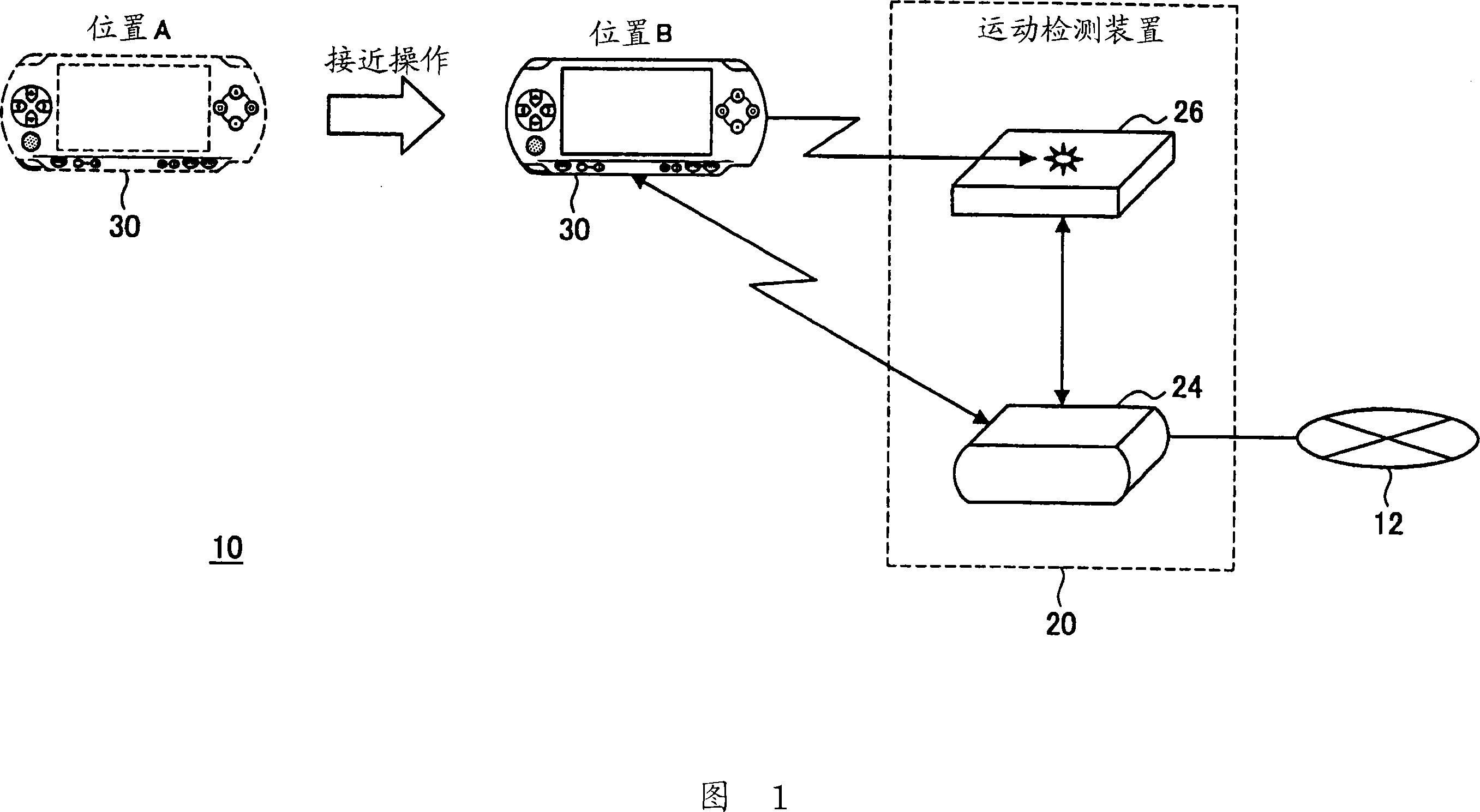
[0039] First, an outline of a motion detection system according to a first embodiment of the present invention will be described with reference to FIG. 1 .

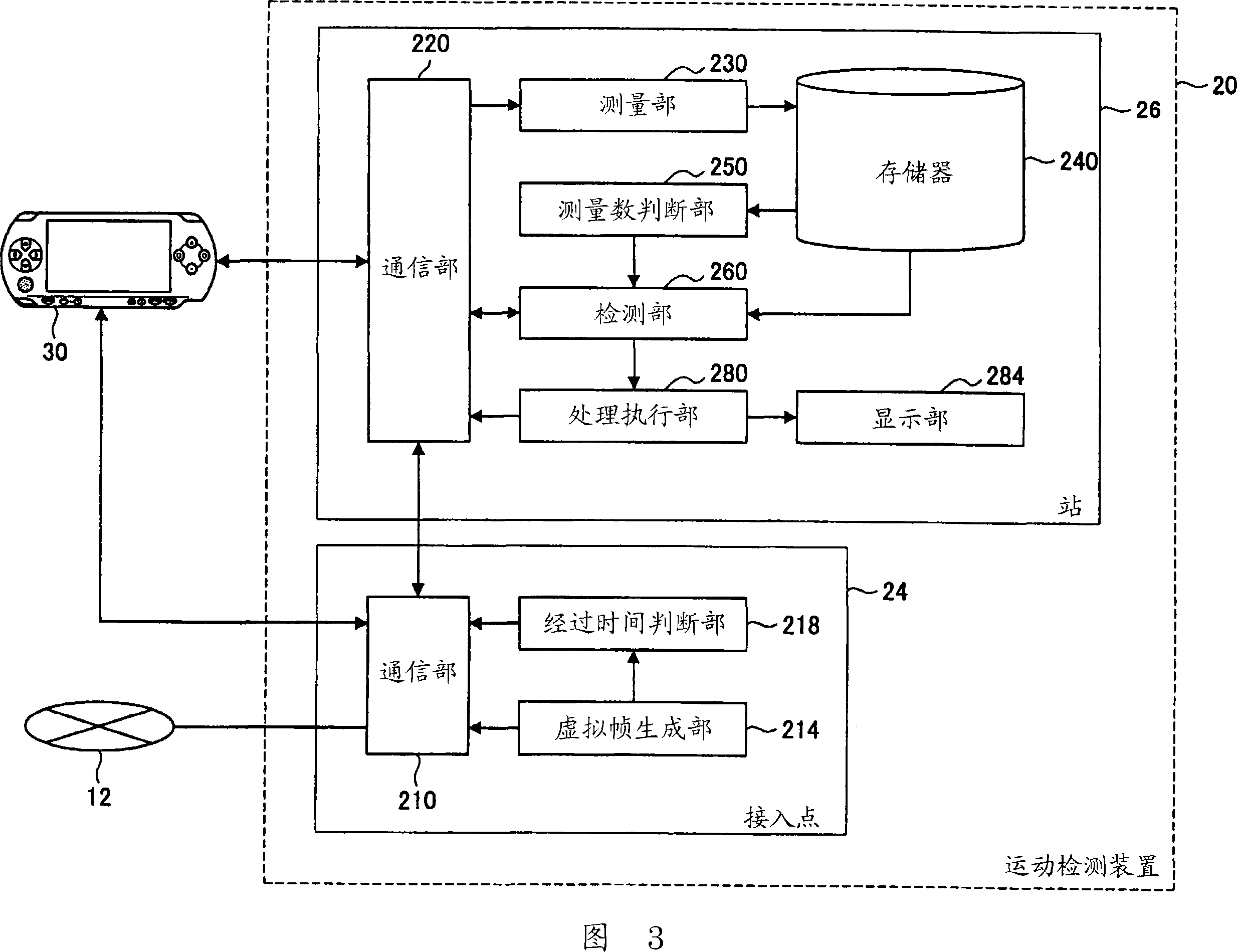
[0040] FIG. 1 is an explanatory diagram showing the configuration of a motion detection system 10 according to the present embodiment. The motion detection system 10 includes a communication network 12 , a motion detection device 20 and a wireless terminal 30 .

[0041] The motion detection device 20 includes an access point 24 and a station 26 . The access point 24 is wired or wirelessly connected to the communication network 12 such as the Internet or Ethernet (registered trademark). In addition, the access point 24 can be connected to the wireless terminal 30 via a wireless LAN (Local Area Network) which is a wireless network, and can function as a base station of the wireless LAN.

[0042] The above-mentioned wireless LAN can be configured based on the wireless network technology defined by the IEEE802.11 series. E...

no. 2 approach

[0115] Next, the motion detection system 10 in the second embodiment of the present invention will be described. The motion detection system 10 in this embodiment differs from the first embodiment in that at least two or more stations 26 are provided as measurement terminals. According to the present embodiment, it is possible to detect a more complex movement of the wireless terminal 30 in space based on this difference. Hereinafter, the motion detection system in this embodiment will be described with reference to FIG. 9 .

[0116] FIG. 9 is an explanatory diagram showing the configuration of the motion detection system 10 in this embodiment. The motion detection system 10 includes a motion detection device 20 including an access point 24 , stations 26A and 26B, and a wireless terminal 30 . The configuration and operation of the access point 24 are substantially the same as those described in the first embodiment, and thus description thereof will be omitted. In addition,...


PUM


Abstract

A movement detection system is provided with a wireless terminal, and a movement detection device connectable to the wireless terminal via a wireless network such that the wireless terminal receives signals used for detection at a predetermined frequency from the movement detection device, and transmits verification signals in response to each of the detection signals. The movement detection device includes a measurement portion that measures the signal strength of the verification signals transmitted by the wireless terminal, and a detection portion that detects spatial movement of the wireless terminal based on the signal strength of the verification signals measured by the measurement portion.

Description

technical field [0001] The invention relates to a motion detection system, a motion detection device, a motion detection method and a computer program. Background technique [0002] In recent years, the trend is that information processing devices such as PCs (Personal Computers) and PDAs (Personal Digital Assistances: Personal Digital Assistants) generally implement the standard specified by IEEE (Institute of Electrical and Electronics Engineers) 802.11 wireless network technology. In addition, there is also a tendency to demand construction of a system that detects the moving speed or spatial movement of an information processing device that functions as such a wireless terminal. [0003] In order to satisfy the above-mentioned requirements, it is conceivable to implement NFC (Near Field Communication) technology, which is an example of short-range wireless technology, in a wireless terminal in a superimposed manner. Here, the NFC (Near Field Communication) technology i...

Claims


Application Information

Patent Timeline
Patent Type & Authority Applications(China)
IPC IPC(8): H04Q7/34H04B17/00
CPCA63F13/12A63F2300/405A63F2300/204A63F2300/1012A63F2300/402A63F2300/205A63F13/30A63F13/327A63F13/31A63F13/92
Inventor 西田佳史
Owner SONY GRP CORP
Learn More