Method for controlling machine tool

A technology of machine tools and control units, applied in the field of controlling machine tools

Inactive Publication Date: 2019-08-09
IVOCLAR VIVADENT AG
View PDF6 Cites 1 Cited by
  • Summary
  • Abstract
  • Description
  • Claims
  • Application Information

AI Technical Summary

Problems solved by technology

But different workpieces also require different tools, so user intervention is still required for tool changes

Method used


Image

  • Method for controlling machine tool
  • Method for controlling machine tool
  • Method for controlling machine tool

Examples


Embodiment Construction

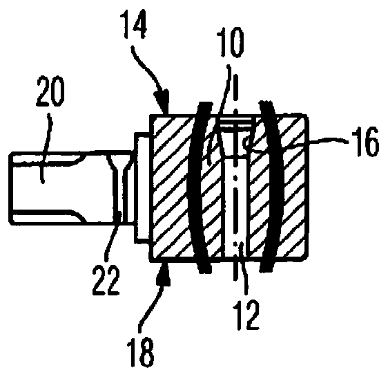
[0039] figure 1 The workpiece 10 shown in has a bore 12 extending transversely through the workpiece. Adjacent to the upper surface 14 is provided a tapered portion 16 of the hole. In contrast, the bore 12 has no taper at the lower surface 18 .

[0040] The workpiece 10 is made of dental ceramics in the exemplary embodiment shown and is placed on a holder 20 . The fixture 20 is used to securely clamp the workpiece in the manipulator, for example, the manipulator consists of Figure 8 visible.

[0041] The holder 20 has a lateral slot 22 which is designed for receiving a workpiece 10 in a workpiece magazine.

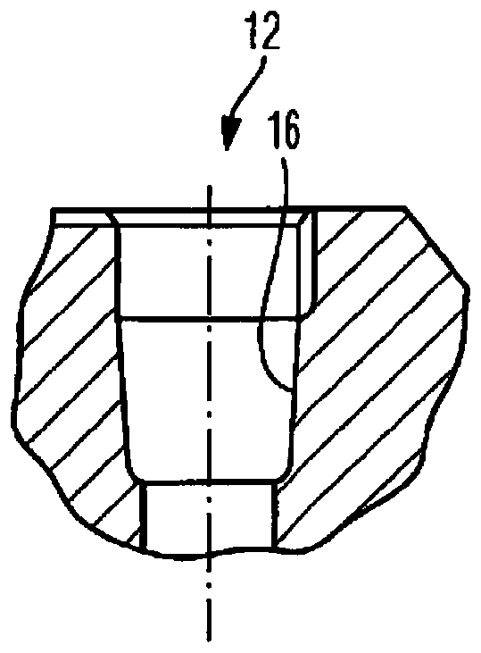
[0042] Depend on figure 2 It can be seen how the conical section 16 can be formed. In the illustrated embodiment, the taper angle is between three and five degrees. If the motion trajectory of the manipulator is chosen such that the sensor detects the surface 14 and the hole extending downwards from this surface, a gradual light / dark transition will occur due to t...


PUM


Abstract

The invention relates to a system composed of a method for controlling a machine tool, and a workpiece, in particular a milling blank, and the method for processing this workpiece, which machine toolhas a robot arm which can move in at least 2, in particular at least 3, spatial axes in a movement range and which holds, guides and moves at least one workpiece, if appropriate by means of a workpiece holder, with a control unit for controlling the machine tool. The machine tool (62) has a sensor, in particular a positionally fixed optical sensor, or the sensor is assigned to said machine tool (62) and its sensing range (66) overlaps at least partially with the movement range. The workpiece (10) has a change in geometry, in particular a hole (12), is moved in the sensing range (66) by the robot arm (70), and when the hole (12) is sensed by the sensor the control unit defines a reference point, reference axis and / or reference face for controlling the machine tool (62).

Description

technical field [0001] The invention relates to a system according to the preambles of claims 1 and 14 comprising a method for controlling a machine tool and a workpiece, in particular a milled blank, and also a method for machining the workpiece. Background technique [0002] Such a system is known, for example, from US 2007 / 111,640 A1. A milling machine of this type has a video device which is installed in a stationary manner. The imaging device is arranged above the tool and has a detection range, the detection range points to the tool. The imaging device should detect the state of the tip of the tool. [0003] Especially for milling machines with a manipulator movable along four or five spatial axes and combined with a fixed tool spindle, it is necessary to respectively determine the basic position of the workpiece relative to the tool. For example, it has been proposed to bring the manipulator and the tool clamped thereto carefully close to the spindle. Due to the c...

Claims


Application Information

Patent Timeline
IPC IPC(8): B23Q17/22B23Q17/24A61C13/00
CPCA61C13/0004B23Q17/2233B23Q17/2428B23Q17/249G05B2219/37555A61C13/0006A61C13/0022
Inventor G·罗纳C·塞勒
Owner IVOCLAR VIVADENT AG
Why Eureka
Try Eureka