
A smart home control device and method based on panoramic view

A smart home control and panoramic view technology, applied in the direction of comprehensive factory control, computer control, electrical program control, etc., can solve the problems of time-consuming and labor-consuming, small image size, high production cost, etc., and achieve easy-to-understand operation and simple and clear interface , Simple effect of human-computer interaction

Active Publication Date: 2017-06-27
XIAMEN LEELEN TECH CO LTD
View PDF11 Cites 0 Cited by
  • Summary
  • Abstract
  • Description
  • Claims
  • Application Information

AI Technical Summary

Problems solved by technology

Although the content of the operation interface established in this way is similar to the actual home structure, there are problems in the three-dimensional structure diagram: 1. The production of the three-dimensional structure diagram is relatively complicated, and it is necessary to make a matching one for each residence with different decoration styles. Three-dimensional structural diagrams are time-consuming, labor-intensive, and costly to produce; 2. Due to the size of the terminal display screen, the image size of the three-dimensional structural diagrams is limited. The structure diagram cannot be displayed one by one, even if it is displayed one by one, the image size of the controlled equipment will be too small, the human-computer interaction is poor, and there is no practical application value; 3. The three-dimensional structure diagram can only be projected inward from one angle , it is impossible to display all the controlled devices in the vertical direction at the incident angle. For example, the 3D structure diagram is projected inward from the angle of the entrance of the gate, but the controlled devices on the wall in the vertical direction at the entrance of the gate cannot be displayed, so It will inevitably cause some controlled equipment to be unable to be reflected in the three-dimensional structure diagram

Method used


Image

  • A smart home control device and method based on panoramic view
  • A smart home control device and method based on panoramic view
  • A smart home control device and method based on panoramic view

Examples


Embodiment Construction

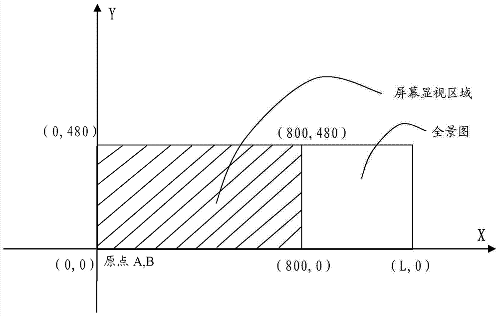
[0048] Such as figure 1 As shown, the smart home control method based on the panoramic view of the present invention comprises the following steps:

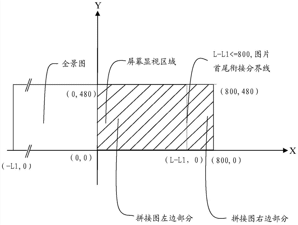
[0049] Step 10. Sequentially take pictures of the interior of the residence room containing several controlled devices, stitch and edit the group of photos into a rectangular panorama with a horizontal 360-degree field of view, and scale the panorama to meet its height. According to the vertical display resolution requirements of the touch screen (that is, the height of the panorama is consistent with the height of the touch screen), the size of the panorama is always greater than or equal to the screen display size, and then a coordinate origin A (0 , 0) (such as figure 2 As shown), with the coordinate origin A (0, 0) as the reference, generate a fixed coordinate set D{d1, d2, d3,...,dn} corresponding to the image area positions of several controlled devices on the panorama;

[0050] Step 20, establishing a control link betwe...


PUM


Abstract

The present invention provides a smart home control device and method based on a panoramic view, which shoots and edits a panoramic view inside a living room; generates a coordinate set of image area positions of controlled equipment in the panoramic view; Control link of the image area of ​​the controlled device; load the panorama to the touch screen to realize seamless splicing and circular display; click the image of the controlled device in the panorama to realize the visual control of the actual controlled device; set the floating shortcut operation button And the pull-down slide-out operation window can quickly and easily establish a vivid and intuitive dynamic real-scene operation interface, which is extremely easy for users to use and greatly saves the cost of engineering construction.

Description

technical field [0001] The invention relates to a smart home control device and method based on a panoramic view user interface. Background technique [0002] Smart home not only has the traditional living function, but also provides a comfortable, safe, high-quality and pleasant family living space, and also transforms the original passive static structure into a tool with dynamic intelligence, providing a full range of information exchange functions. Help families maintain smooth communication with the outside world, optimize people's lifestyles, help people effectively arrange time, enhance the safety of home life, and even save money for various energy costs. [0003] At present, some user operation interfaces used in smart home control devices are displayed in a one-dimensional interface. There are a number of buttons on the operation interface, and they are equipped with patterns or characters, indicating the controlled equipment in the home such as air conditioners an...

Claims


Application Information

Patent Timeline
Patent Type & Authority Patents(China)
IPC IPC(8): G05B19/418G05B15/02G06F3/0488
Inventor 王远春洪锦彬林斌峰
Owner XIAMEN LEELEN TECH CO LTD
Learn More