Dynamic proxy system and method of target relation mapping system

A technology of object-relational mapping and dynamic proxy, applied in the computer field

Inactive Publication Date: 2014-12-03
利德科技发展有限公司 +1
View PDF2 Cites 6 Cited by
  • Summary
  • Abstract
  • Description
  • Claims
  • Application Information

AI Technical Summary

Problems solved by technology

However, with the continuous development of enterprise applications, the mapping scheme of business requirements to ORM systems no longer stays at the level of static mapping. In the face of massive user data and large-scale enterprise applications with high access volume, many systems use sub-database and sub-table architecture, some applications still have the need for customer-defined fields in the later stage of system launch
If a system adopts a sub-table strategy according to business needs (for example, e-commerce systems u

Method used


Image

  • Dynamic proxy system and method of target relation mapping system
  • Dynamic proxy system and method of target relation mapping system
  • Dynamic proxy system and method of target relation mapping system

Examples


Embodiment Construction

[0027] In order to understand the above-mentioned purpose, features and advantages of the present invention more clearly, the present invention will be further described in detail below in conjunction with the accompanying drawings and specific embodiments. It should be noted that, in the case of no conflict, the embodiments of the present application and the features in the embodiments can be combined with each other.

[0028] In the following description, many specific details are set forth in order to fully understand the present invention, but the present invention can also be implemented in other ways different from those described here, therefore, the present invention is not limited to the specific embodiments disclosed below limit.

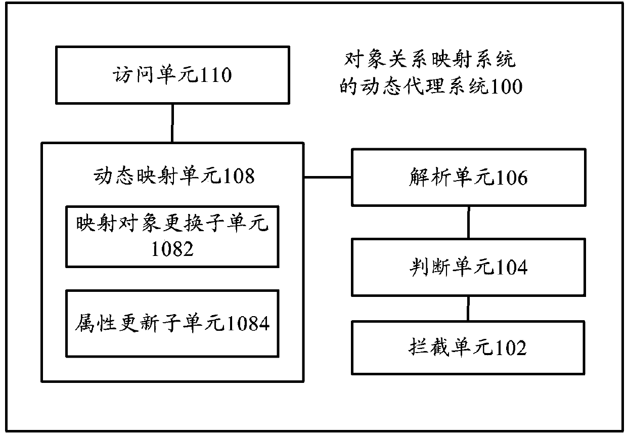
[0029] figure 1 A schematic diagram showing a dynamic proxy system of an object-relational mapping system according to an embodiment of the present invention.

[0030] Such as figure 1 As shown, the dynamic proxy system 100 of the objec...


PUM


Abstract

The invention provides a dynamic proxy system of a target relation mapping system. The dynamic proxy system comprises an interception unit, a judging unit, an analyzing unit, a dynamic mapping unit and an access unit, wherein the interception unit is used for intercepting a mapping request which is generated according to a data request sent by a client to a server; the judging unit is used for judging whether dynamic mapping support is required to be provided to the mapping request or not; the analyzing unit is used for analyzing mapping parameters according to the mapping request when the dynamic mapping support is required to be provided; the dynamic mapping unit is used for dynamically mapping a target model and a relation data model in the target relation mapping system according to the mapping parameters; the access unit is used for performing data access on the basis of the target model which is dynamically mapped and feeding an access result back to the client. Correspondingly, the invention also provides a dynamic proxy method of the target relation mapping system. The dynamic proxy method of the target relation mapping system is provided to the target model during operation from transverse and longitudinal dimensions, so that the method can be well combined with the traditional static mapping scheme of the target relation mapping system.

Description

technical field [0001] The invention relates to the field of computer technology, in particular to a dynamic agent system of an object-relational mapping system and a dynamic agent method of the object-relational mapping system. Background technique [0002] In object-oriented (OO) software product design, when designers face relational database management systems composed of relational databases such as MySQL, MSSQL, and ORACLE, object-relational mapping schemes (ORM, Object / Relation Mapping) gradually become mainstream technology. The ORM system manages the relationship between the relational data model and the object model (Object Model). Usually, the relational data model (NRDM) corresponds to the object model one by one. The structure of a table in NRDM corresponds to the structure of an entity class in the object model. The fields in the table correspond to the attributes of the entity object, and a row of records in the table corresponds to an entity object (Entity O...

Claims


Application Information

Patent Timeline
IPC IPC(8): G06F17/30G06F9/44
CPCG06F16/86G06F16/288
Inventor 郑伟黄科
Owner 利德科技发展有限公司
Why Eureka
Try Eureka