Pupil detection method and device

A detection method and detection device technology, applied in character and pattern recognition, instruments, computer parts and other directions, can solve problems such as pupil position deviation, pupil center positioning accuracy interference, etc., achieve accurate pupil center, improve accuracy and robustness Effect

Inactive Publication Date: 2014-12-03
BEIJING SAMSUNG TELECOM R&D CENT +1
View PDF0 Cites 20 Cited by
  • Summary
  • Abstract
  • Description
  • Claims
  • Application Information

AI Technical Summary

Problems solved by technology

When the frame rate of the camera is not high, the movement of the head and eyeballs will cause the pupil position deviation in the bright pupil and dark pupil images;

Method used


Image

  • Pupil detection method and device
  • Pupil detection method and device
  • Pupil detection method and device

Examples


Embodiment Construction

[0035] Embodiments of the present invention will be described in detail below with reference to the accompanying drawings. Throughout the drawings, like reference numerals denote like structures, features, and elements.

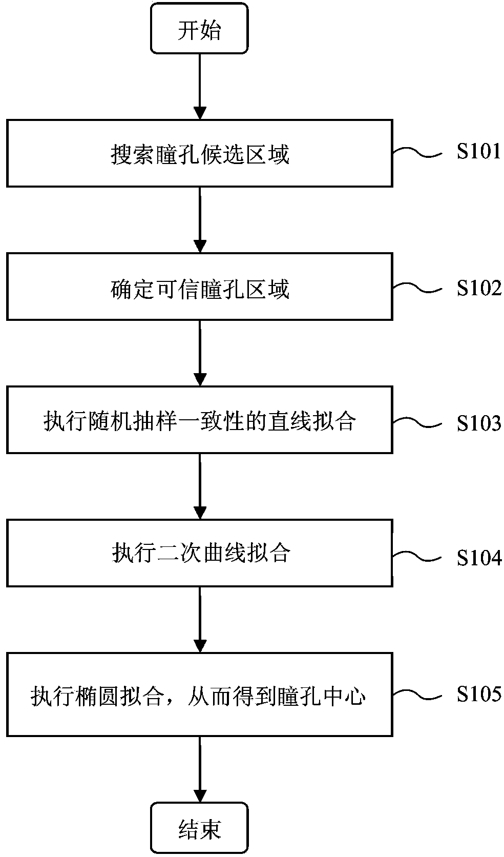
[0036] figure 1 is a flowchart illustrating a pupil detection method according to an embodiment of the present invention.

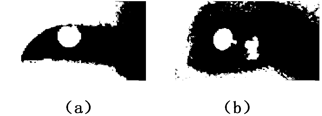
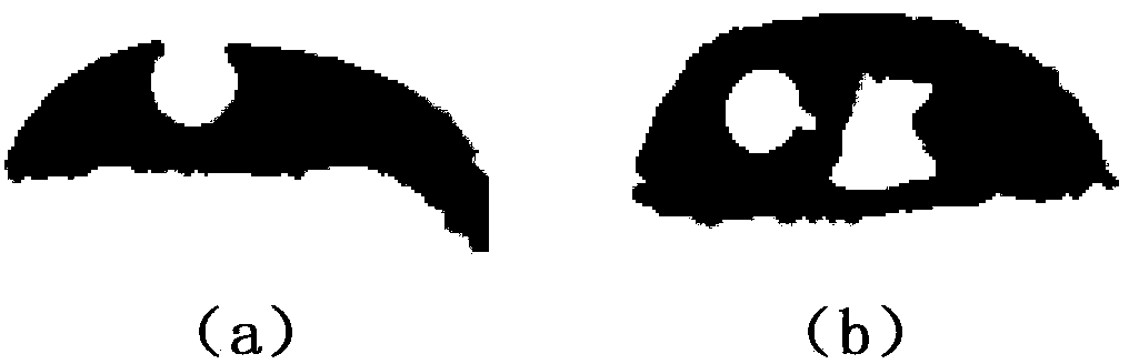
[0037] refer to figure 1 , in step S101, in the bright pupil image taken by the infrared camera, search for the area of ​​the "black-white-black" structure pattern line by line and pixel by line as the pupil candidate area, and record the edge points of the pupil candidate area and each row of white lines midpoint of . In actual processing, step S101 can only be performed after performing local binarization and morphological filtering on the captured bright pupil image. figure 2Eye regions in two bright-pupil images captured by an infrared camera are shown. exist figure 2 (a) shows the eye area occluded by the eyelids, in figur...


PUM


Abstract

Disclosed are a pupil detection method and device. The pupil detection method includes the following steps: searching for areas of a black-white-black structural mode in a shot bright pupil image line by line and pixel by pixel and using the areas as pupil candidate areas and recording edge points and a midpoint of each line of white line of the pupil candidate areas; according to the circularity and average grey degree of each pupil candidate area, determining a trustable pupil area; executing random sample consensus linear fitting on midpoints of the white lines of the determined trustable pupil area so that reliable midpoints of the white lines of the trustable pupil area and edge points corresponding to the reliable midpoints are obtained; executing second curve fitting on the edge points corresponding to the reliable midpoints so that reliable edge points of the trustable pupil area are obtained; and carrying out elliptic fitting on the reliable edge points of the trustable pupil area so that a pupil center is obtained.

Description

technical field [0001] The present invention relates to a pupil detection method and device, more specifically, to a pupil detection method and device for improving the accuracy and robustness of pupil positioning by using bright pupil images to detect pupils. Background technique [0002] Eyes are the main window for human beings to obtain information from the outside world, and the information it receives accounts for 80% to 90% of all information received by the brain. Gaze is the direction in which the eyes are looking, and it represents the focus of a person's attention. Gaze tracking has been an active research topic in recent decades. Gaze tracking has great application potential in the field of human-computer interaction. For example, when the user gazes at the display screen, the gaze point of the user on the screen can be estimated by a gaze tracking system. As a result, gaze can be used as a means of advanced computer input, which has proven to be more efficien...

Claims


Application Information

Patent Timeline
IPC IPC(8): G06K9/00
Inventor 高书征王西颖
Owner BEIJING SAMSUNG TELECOM R&D CENT
Why Eureka
Try Eureka