Direct-current power flow controller for multiport flexible direct-current power transmission system and control method

A technology of direct current transmission system and direct current flow, which is applied in the direction of direct current network circuit devices, electrical components, circuit devices, etc., can solve the problem of many switching devices, achieve fewer switching devices, improve control capabilities, transmission line transmission capacity, and circuit structure simple effect

Inactive Publication Date: 2014-12-03
SOUTHEAST UNIV
View PDF5 Cites 26 Cited by
  • Summary
  • Abstract
  • Description
  • Claims
  • Application Information

AI Technical Summary

Problems solved by technology

However, the circuit structure of these two schemes requires an external power supply to provide power for the adjustable voltage source or absorb

Method used


Image

  • Direct-current power flow controller for multiport flexible direct-current power transmission system and control method
  • Direct-current power flow controller for multiport flexible direct-current power transmission system and control method
  • Direct-current power flow controller for multiport flexible direct-current power transmission system and control method

Examples


Example Embodiment

[0038] Example 1 and Example 2 both adopt figure 1 In the three-terminal ring network flexible DC transmission system shown, VSC3 operates in constant DC voltage mode, and controls V 3 =150kV, VSC1 and VSC2 operate in constant power mode, respectively inject P into the system 1 = 160MW and P 2 =80MW power, the parameters of the three-section transmission line are shown in Table 1.

[0039] Table 1 figure 2 Line parameters of the three-terminal flexible DC transmission system shown

[0040] Transmission line parameters

[0041] The transmission line current and the adjustable voltage source voltage V after adding the DC power flow controller of the present invention x , V y The relationship curve is like Picture 10 As shown, the port voltage V 1 , V 2 With adjustable voltage source voltage V x , V y The relationship curve is like Picture 11 Shown.

[0042] Example 1 is to make the power P injected into the system by VSC2 2 Jump from 80MW to 50MW, maintain I 23 It is unchanged a...

Example Embodiment

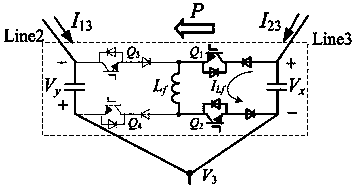
[0043] Example 2 is that the power P is first determined by V y Pass to V x , After a period of time by V x Pass to V y , Power P by V y Pass to V x 时,Maintain current I 13 Is 0.32kA, power P by V x Pass to V y 时,Maintain current I 23 It is 0.35kA. Figure 15 The current waveform of the transmission line before and after the transmission direction of the power P is changed is given, Figure 16 The port voltage V before and after the transmission direction of the power P is changed is given 1 And V 2 的waveform. by Figure 15 It can be seen that when the transmission direction of the power P of the power flow controller changes, the currents on the three lines have changed, and the DC power flow in Line 1 has reversed. It shows that the power flow controller of the present invention can meet the needs of power flow reversal.


PUM


Abstract

The invention discloses a direct-current power flow controller for a multiport flexible direct-current power transmission system and a control method. The direct-current power flow controller comprises two adjustable voltage sources which are respectively connected in two adjacent power transmission lines in series, wherein two by-pass switches are respectively in parallel connection with the two adjustable voltage sources, and four switch tubes and four diodes are distributed on two sides of an inductor after being connected in series. Current of the power transmission line where a certain adjustable voltage source is located is acquired and subtracted from a given current reference value and then is subtracted from acquired voltage of the adjustable voltage source after a PI link and a delay link, PWM drive signals of the switch tubes are obtained by performing the PI link on a difference value, and turning-on and turning-off of the switch tubes are controlled to enable the current of the power transmission line where the adjustable voltage source to serve as a given reference value. The direct-current power flow controller is simple in circuit structure, is provided with few switch devices and does not need an isolation transformer and an external power supply.

Description

technical field [0001] The invention relates to a direct current flow controller, which belongs to the technical field of power electronics and is mainly used in multi-terminal direct current transmission occasions. Background technique [0002] The multi-terminal direct current transmission system is a direct current transmission system consisting of three or more converter stations connected in series, parallel or hybrid. It can realize multi-source power supply and multi-drop power reception. The operation of the system is more economical and flexible, and it is one of the effective technical means to solve the problems of large-scale renewable energy grid integration, large-capacity long-distance power transmission and shortage of transmission corridors that my country is currently facing. Compared with the traditional current source converter, the voltage source converter (voltage source converter, VSC) reverses the direction of the DC current while the polarity of the c...

Claims


Application Information

Patent Timeline
IPC IPC(8): H02J1/00H02J3/36
CPCY02E60/60
Inventor 陈武朱旭
Owner SOUTHEAST UNIV
Why Eureka
Try Eureka