
A harvester rotates a large granary

A harvester and granary technology, applied in harvesters, cutters, agricultural machinery and implements, etc., can solve the problems of inconvenient logistics and transportation, large deformation of columns, and low maintenance efficiency, and achieve easy transportation and disassembly, small deformation, and strength. Good results

Active Publication Date: 2016-05-18
LIUZHOU WULING LIUJI POWER
View PDF6 Cites 0 Cited by
  • Summary
  • Abstract
  • Description
  • Claims
  • Application Information

AI Technical Summary

Problems solved by technology

[0002] At present, there are many types of harvesters with rotating large granaries on the market, but these harvesters mainly have the following disadvantages: 1. One end of the hydraulic cylinder is installed on the chassis, and the other end is installed on the unloading barrel. In the process of turning out and turning in, it is necessary to disassemble and assemble multiple components such as wiring harnesses and hydraulic cylinders, which is inconvenient to rotate and the maintenance efficiency is low; 2. During the turning out process, the rotating large granary is suspended in the air, and the column supporting the rotating large granary bears a large force and the column deforms greatly ;3. The uprights supporting the large rotating granary are usually directly welded on the chassis, and cannot be disassembled to make logistics and transportation inconvenient;

Method used


Image

  • A harvester rotates a large granary
  • A harvester rotates a large granary
  • A harvester rotates a large granary

Examples


Embodiment Construction

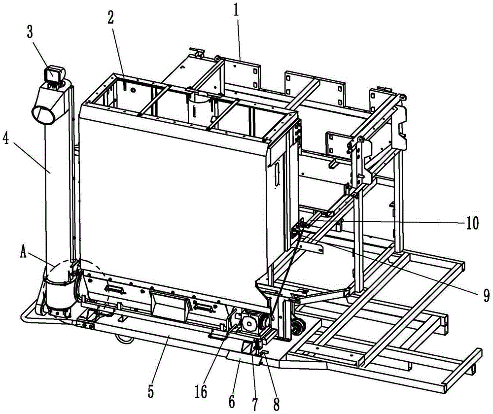
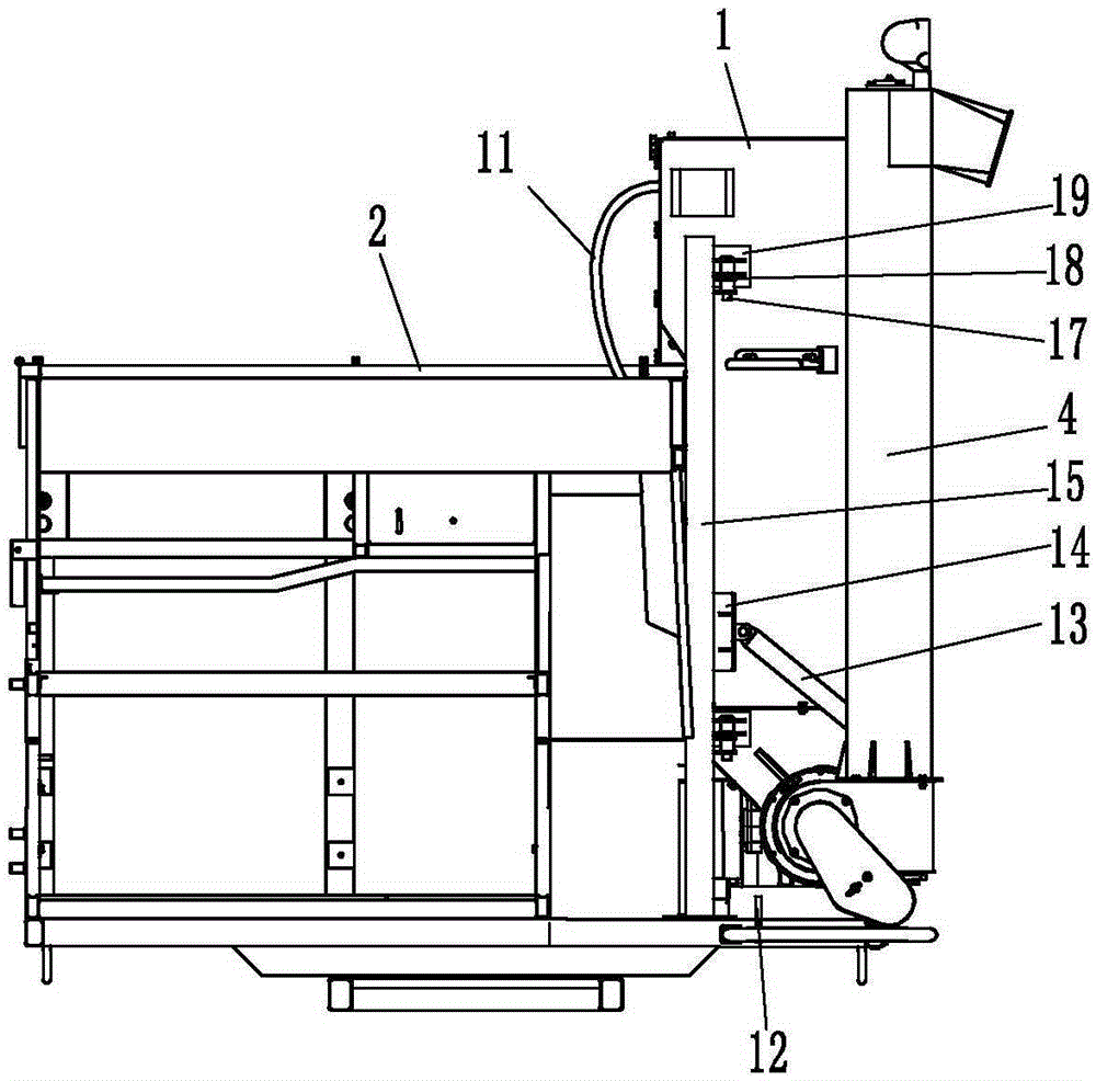
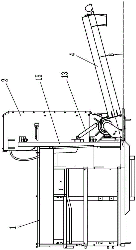
[0028] Such as Figure 1 to Figure 9 As shown, the harvester of the present invention rotates a large granary, and the rotary large granary includes a non-rotating device and a rotating device.

[0029] The non-rotating device includes a column welding 15, a granary transfer-in limiter, and a granary transfer-out limiter. Described column welding 15 comprises column 31, the bottom fara plate 32 that is connected at the bottom of column 31, the column hinge seat 18 that is connected at one side of column 31, as Image 6 As shown, in the present embodiment, there are two column hinge seats 18, the number of column hinge seats 18 can be set in different quantities according to the size of the harvester, and the upper side of the column welding 15 is fixedly connected to the harvester thresher by bolts After the afterbody of cleaning frame 1, the bottom flange plate 32 of column welding 15 lower ends is fastened and connected on the harvester chassis 5 with bolts. The granary is...


PUM


Abstract

The invention discloses a novel harvester rotating large barn and relates to the technical field of agricultural machinery. The novel harvester rotating large barn comprises a non-rotating device and a rotating device. The non-rotating device comprises a stand column welding part, a barn rotating-in limiting piece and a barn rotating-out limiting piece. The stand column welding part comprises a stand column, a bottom farad plate and a stand column hinge base. The upper side of the stand column welding part is fixedly connected to the tail of a threshing sorting frame, and the lower end of the stand column welding part is fixedly connected to a bottom disc. The rotating device comprises a barn body, a barn rotating supporting device, an unloading cylinder, a hydraulic oil cylinder and a wire harness. The barn hinge base of the barn body is hinged to the stand column hinge base through a pin shaft, so that the barn body is connected to one side of the stand column in a rotatable mode. The barn rotating supporting device is fixedly connected to the bottom of the barn body. The unloading cylinder is connected to the lower end of the barn body in a rotatable mode. One end of the hydraulic oil cylinder is connected with the barn body. The other end of the hydraulic oil cylinder is connected with the unloading cylinder. The wire harness enters the barn body through a wire harness hole in the side wall of one side, close to the threshing sorting frame, of the barn body via one side of the threshing sorting frame.

Description

technical field [0001] The invention relates to the technical field of agricultural machinery, in particular to a granary for harvesters. Background technique [0002] At present, there are many types of harvesters with rotating large granaries on the market, but these harvesters mainly have the following disadvantages: 1. One end of the hydraulic cylinder is installed on the chassis, and the other end is installed on the unloading barrel. In the process of turning out and turning in, it is necessary to disassemble and assemble multiple components such as wiring harnesses and hydraulic cylinders, which is inconvenient to rotate and the maintenance efficiency is low; 2. During the turning out process, the rotating large granary is suspended in the air, and the column supporting the rotating large granary bears a large force and the column deforms greatly ; 3. The columns supporting the large rotating granary are usually directly welded on the chassis, and cannot be dismantled...

Claims


Application Information

Patent Timeline
Patent Type & Authority Patents(China)
IPC IPC(8): A01D41/12A01F12/60
Inventor 李军林覃文龙郑长鹏何佑之张世珍梁宇宁
Owner LIUZHOU WULING LIUJI POWER
Learn More