Double-chain driven sludge scraper

A technology of double chain and mud scraper, which is applied to the feeding/discharging device, chemical instrument and method, and separation method of the settling tank, which can solve the problem of low separation efficiency of sludge and clarified water and the structure of reciprocating mud scraper Complicated, affecting sludge treatment efficiency and other issues, to achieve the effect of simple structure, convenient safety and maintenance, stable wear-resistant service life

Inactive Publication Date: 2014-12-10
JINGJIN ENVIRONMENTAL PROTECTION INC
View PDF4 Cites 2 Cited by
  • Summary
  • Abstract
  • Description
  • Claims
  • Application Information

AI Technical Summary

Problems solved by technology

[0003] Most of the mud scrapers currently used are reciprocating, but in the field use, it is found that there are deficiencies. Due to the structure of the reciprocating operation of the mud scraper, it is easy to redissolve the concentrated and precipitated sludge into the sewage, making the sediment The separation efficiency of sludge and clarified water is low, and the sludge cannot normally enter the sludge tank and be discharged by the sludge suction machine. The reciprocating sludge scraper has a complex structure and often breaks down, and it is inconvenient to maintain. At the same time, the service life is short and the efficiency is low, which affects the sludge. Processing efficiency

Method used


Image

  • Double-chain driven sludge scraper
  • Double-chain driven sludge scraper
  • Double-chain driven sludge scraper

Examples


Embodiment Construction

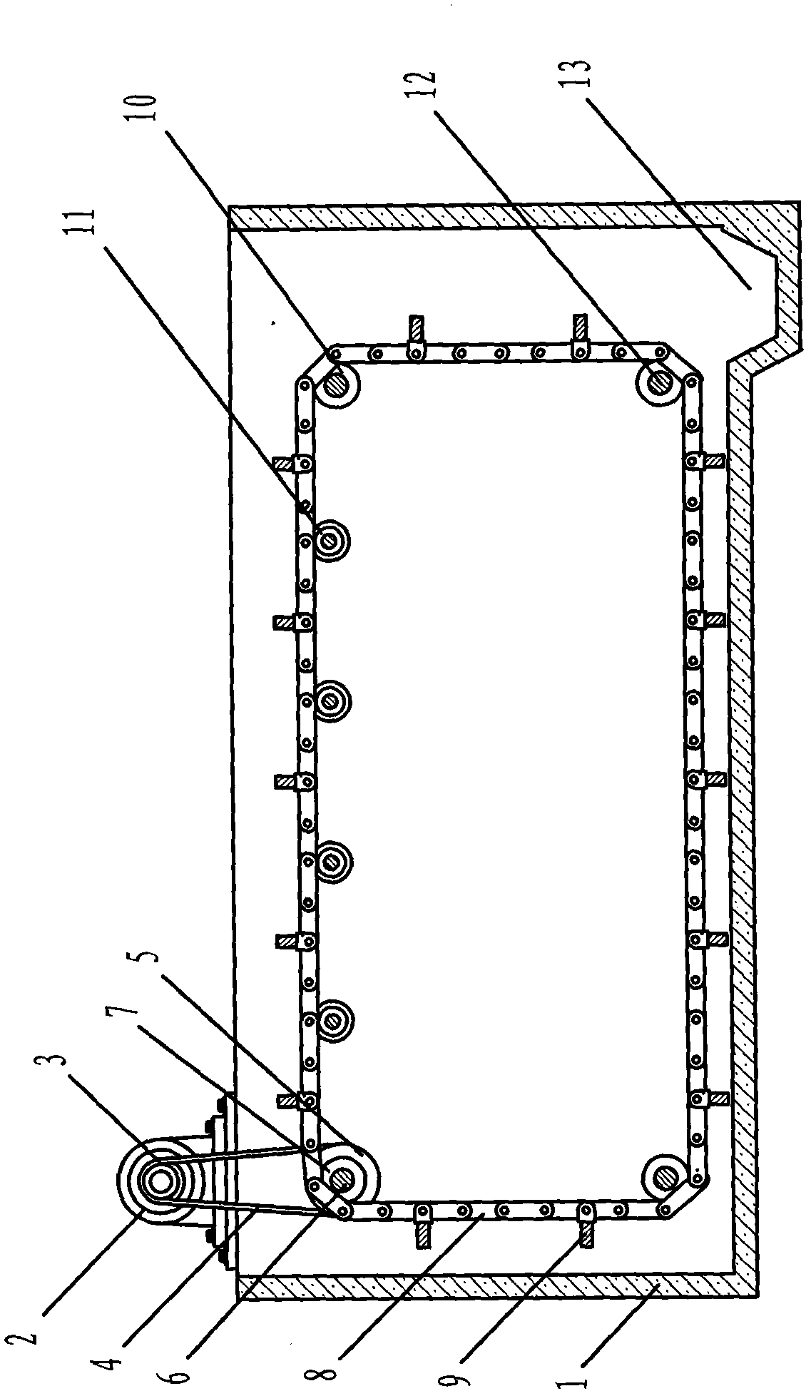
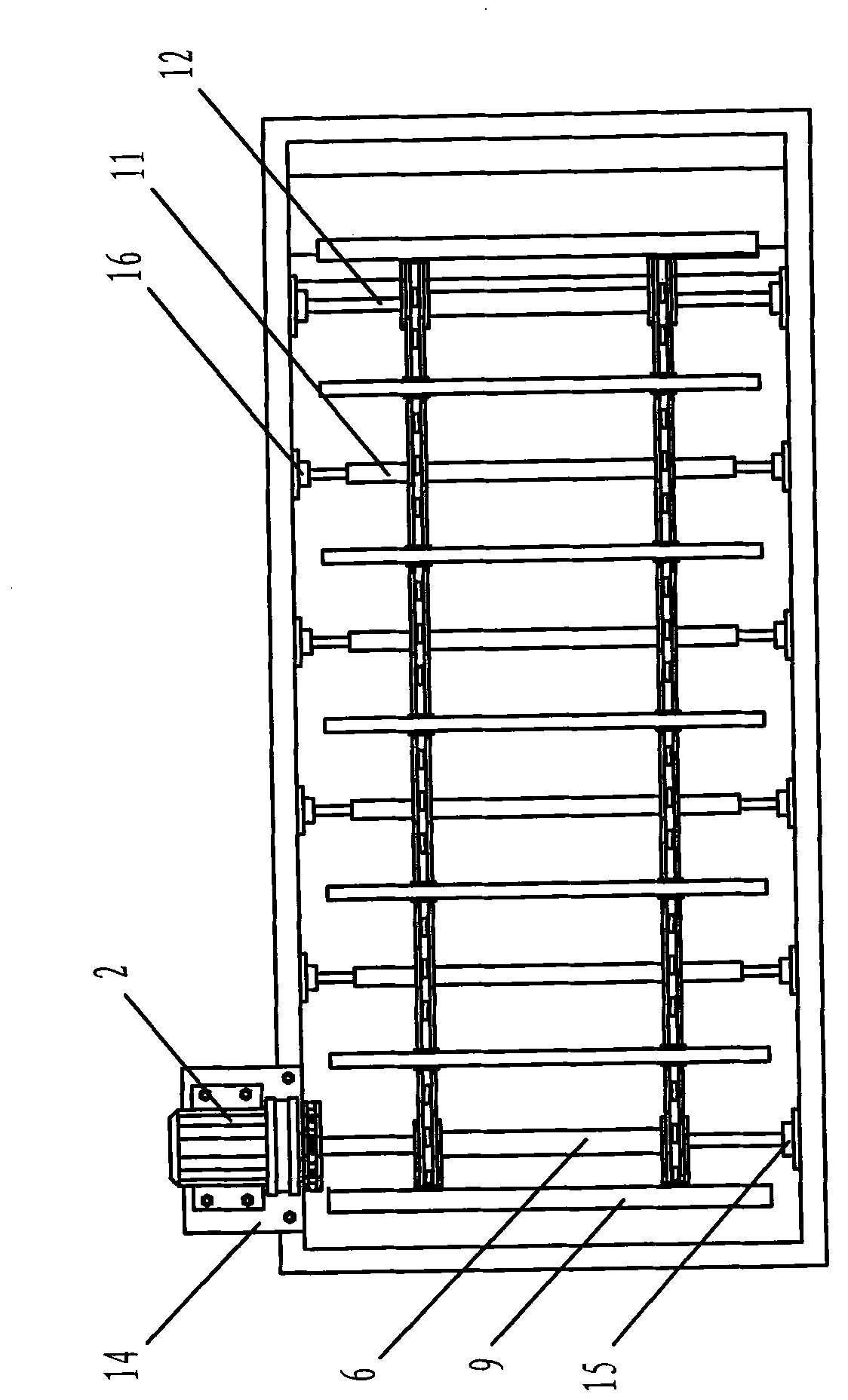
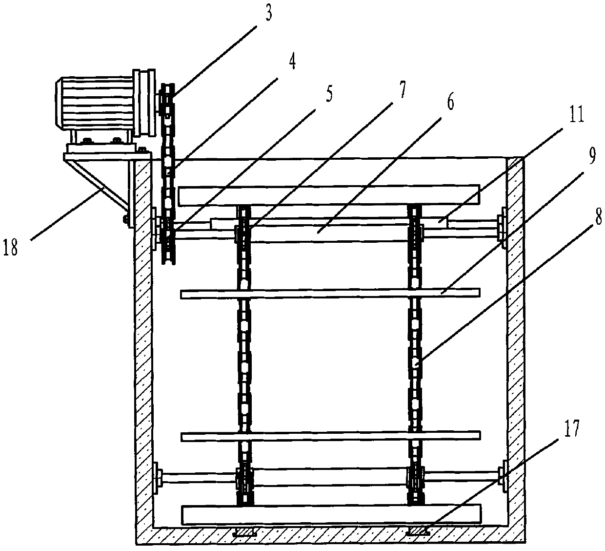
[0016] See Figure 1 to Figure 5 As shown, the present invention provides a double-chain driven mud scraper. A motor base 14 is installed at the upper end of the sedimentation tank 1. The motor base 14 is provided with a tripod 18 and is installed on the wall of the sedimentation tank 1 made of concrete using expansion bolts. The material used to make the motor base 14 and the tripod 18 is carbon structural steel, which is formed by welding. The geared motor 2 is installed on the motor base 14. The control cabinet of the geared motor 2 is equipped with an overload self-stop safety device. The sprocket 3 is provided with a driving shaft 6 on the upper side of the sedimentation tank 1, and the driving shaft 6 and the driven shaft 12 are made as a welding combination, which is machined after welding. The two ends of the driving shaft 6 and the driven shaft 12 are welded for use The material is carbon structural steel, and the material used in the middle welding is seamless steel p...


PUM


Abstract

The invention discloses a double-chain driven sludge scraper. A motor base is arranged on the upper surface of a settling pool and is provided with a tripod which is arranged in the settling pool; a speed reducer is arranged on the upper surface of the motor base and is provided with a small chain wheel; a driving shaft is arranged at the upper side in the settling pool; a big chain wheel is arranged at one end of the driving shaft; a transmission chain is arranged for connecting the small and big chain wheels; the driving shaft is provided with a driving chain wheel; bearing boxes are arranged at two ends of the driving shaft and are arranged on the wall of the settling pool; driven shafts are arranged at the upper and lower sides of the settling pool and are provided with driven chain wheels; bearing boxes are arranged two ends of each driven shaft and are arranged on the wall of the settling pool; a chain is arranged for connecting the driving chain wheels and the driven chain wheels; a sludge scraping plate is arranged on the upper surface of the chain; a welding connecting element of the sludge scraping plate is arranged on the upper surface of the chain by virtue of a pin roll; a support roller is arranged at the lower surface of the chain at the upper side of the settling pool; wear resistant parts are arranged at the bottom of the settling pool; a sludge groove is arranged at one end of the bottom of the settling pool; the speed reducer is arranged on the upper surface of the motor base and a control cabinet of the speed reducer is provided with a safety device for self-stopping when the reducer is overloaded.

Description

Technical field [0001] The invention belongs to the field of sewage sludge treatment equipment, and relates to a mud scraper, and more particularly, to a mud scraper driven by a double chain. Background technique [0002] The scraper is the main equipment for sewage sludge treatment. The scraper is widely used in the urban and rural environmental protection sewage sludge treatment industry. The sedimentation tank installed by the scraper is generally made of concrete or metal plate welding materials. The bottom of the scraper is equipped with Sludge tank, the sewage sludge enters the sedimentation tank based on the gravity sedimentation of solid particles or the use of drugs to thicken the upper part of the clarified water and the lower part of the sedimentation sludge slurry. The sludge scraper can suck the sedimented sludge through the sludge tank through the pipeline. The mud machine is discharged from the sedimentation tank, and then the next step is performed according to th...

Claims


Application Information

Patent Timeline
IPC IPC(8): B01D21/18B01D21/24
Inventor 宋伟杨名杰柳宝昌刘国治
Owner JINGJIN ENVIRONMENTAL PROTECTION INC
Why Eureka
Try Eureka