Reverse multi-point swirl jet denitrification device

A multi-point, denitration technology, applied in the direction of dispersed particle separation, chemical instruments and methods, separation methods, etc., can solve the problems of insufficient mixing and low flue gas removal efficiency, and achieve the effect of accelerating efficiency

Active Publication Date: 2016-03-23
山东志伟环保科技有限公司
View PDF5 Cites 0 Cited by
  • Summary
  • Abstract
  • Description
  • Claims
  • Application Information

AI Technical Summary

Problems solved by technology

[0004] Aiming at the problems of insufficient mixing and low flue gas removal efficiency in the existing flue gas denitrification technology, the present invention provides a reverse multi-point swirl jet denitrification device

Method used


Image

  • Reverse multi-point swirl jet denitrification device
  • Reverse multi-point swirl jet denitrification device
  • Reverse multi-point swirl jet denitrification device

Examples


Embodiment Construction

[0018] The present invention will be further described and defined below in conjunction with the accompanying drawings.

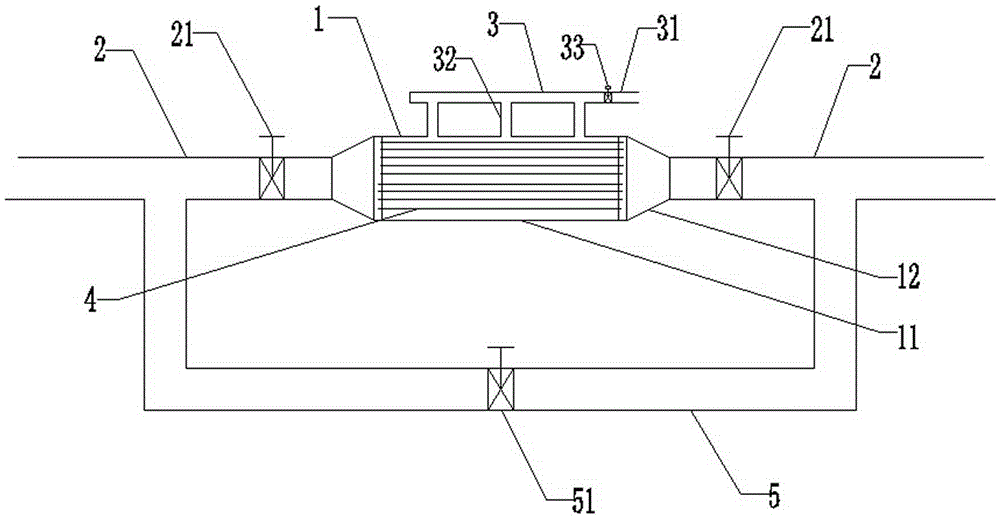
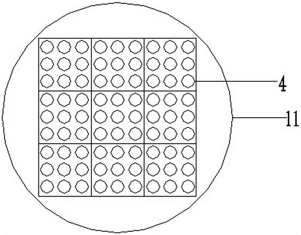
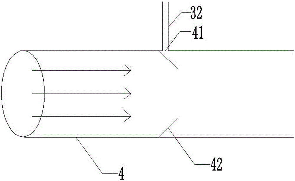
[0019] Such as figure 1 with 2 As shown, a reverse multi-point swirl jet denitration device includes a reverse multi-point swirl injector 1 for flue gas denitrification, and a flue gas connected to the inlet and outlet ends of the reverse multi-point swirl injector 1. The gas channel 2 and the denitration agent channel 3 communicated with the interior of the reverse multi-point swirl injector 1; the reverse multi-point swirl injector 1 is provided with 81 swirl tubes 4 parallel to its axis, and 81 swirl tubes The tubes 4 are arranged in a 9*9 array, and each swirl tube 4 is provided with a denitrification agent inlet 41 connected to the denitrification agent channel 3, and the denitrification agent inlet 41 is provided on the side close to the intake end of the reverse multi-point swirl injector 1 Two vertically symmetrical inclined swirl plates 42 . The...


PUM


Abstract

The invention discloses a reverse multi-point swirl-injection denitrating device. The reverse multi-point swirl-injection denitrating device comprises a reverse multi-point swirl injector for denitrating flue gas, a flue gas passage communicated with the gas inlet end and the gas outlet end of the reverse multi-point swirl injector, and a denitrating agent passage communicated with the interior of the reverse multi-point swirl injector, wherein a plurality of swirl tubes parallel to the axis of the reverse multi-point swirl injector are arranged inside the reverse multi-point swirl injector; a denitrating agent inlet communicated with the denitrating agent passage is arranged on each swirl tube; two inclined swirl plates which are vertically symmetrical are arranged on the side, near the gas inlet end of the reverse multi-point swirl injector, of each denitrating agent inlet. The reverse multi-point swirl-injection denitrating device can mix the flue gas and the denitrating agent thoroughly, so that the problem that the flue gas removing efficiency is low is solved.

Description

technical field [0001] The invention relates to a reverse multi-point swirl jet denitrification device, which belongs to the technical field of high-efficiency flue gas denitrification. Background technique [0002] Currently NO X Emissions and atmospheric NO X The rapid increase of concentration has caused a series of urban and regional environmental problems, posing a huge threat to human health and ecological environment. [0003] At present, the selective catalytic reduction method (SCR method) and the selective non-catalytic reduction method (SNCR method) are widely used in domestic and foreign flue gas denitrification technologies. The selective catalytic reduction method is to convert ammonia (NH 3 ) and other reducing agents are injected into the flue to mix with the flue gas, NH 3 Under catalytic conditions, it can convert NO X Reduced to nitrogen, so that NO in the flue gas X content decreased. The selective non-catalytic reduction method is to convert ammon...

Claims


Application Information

Patent Timeline
Patent Type & Authority Patents(China)
IPC IPC(8): B01D53/79B01D53/90B01D53/56
Inventor 牛志宝
Owner 山东志伟环保科技有限公司
Why Eureka
Try Eureka