Stamping device

A punching equipment and punching technology, applied in the field of punching equipment, can solve the problems of low punching efficiency, unfavorable plate processing, and time-consuming, etc., and achieve the effect of high processing efficiency and reduction of punching time.

Active Publication Date: 2014-12-10
ZHEJIANG ZHONGGUANG ELECTRIC CO LTD
View PDF7 Cites 8 Cited by
  • Summary
  • Abstract
  • Description
  • Claims
  • Application Information

AI Technical Summary

Problems solved by technology

[0002] Existing stamping machine tools punch each hole separately when punching the plate, while the turret-type punching machine can be equipped with multiple molds, which can realize continuous punching of multiple common holes of various specifications on the same plate. hole, but after punching a hole, the mold has to move one or several stations, the process of mold transposition takes a lot of time, and the overall stamping efficiency is still low
Especially not conducive to the processing of large quantities of plates

Method used


Image

  • Stamping device
  • Stamping device
  • Stamping device

Examples


Embodiment Construction

[0016] A detailed description will be given below of specific embodiments of the present invention according to the accompanying drawings.

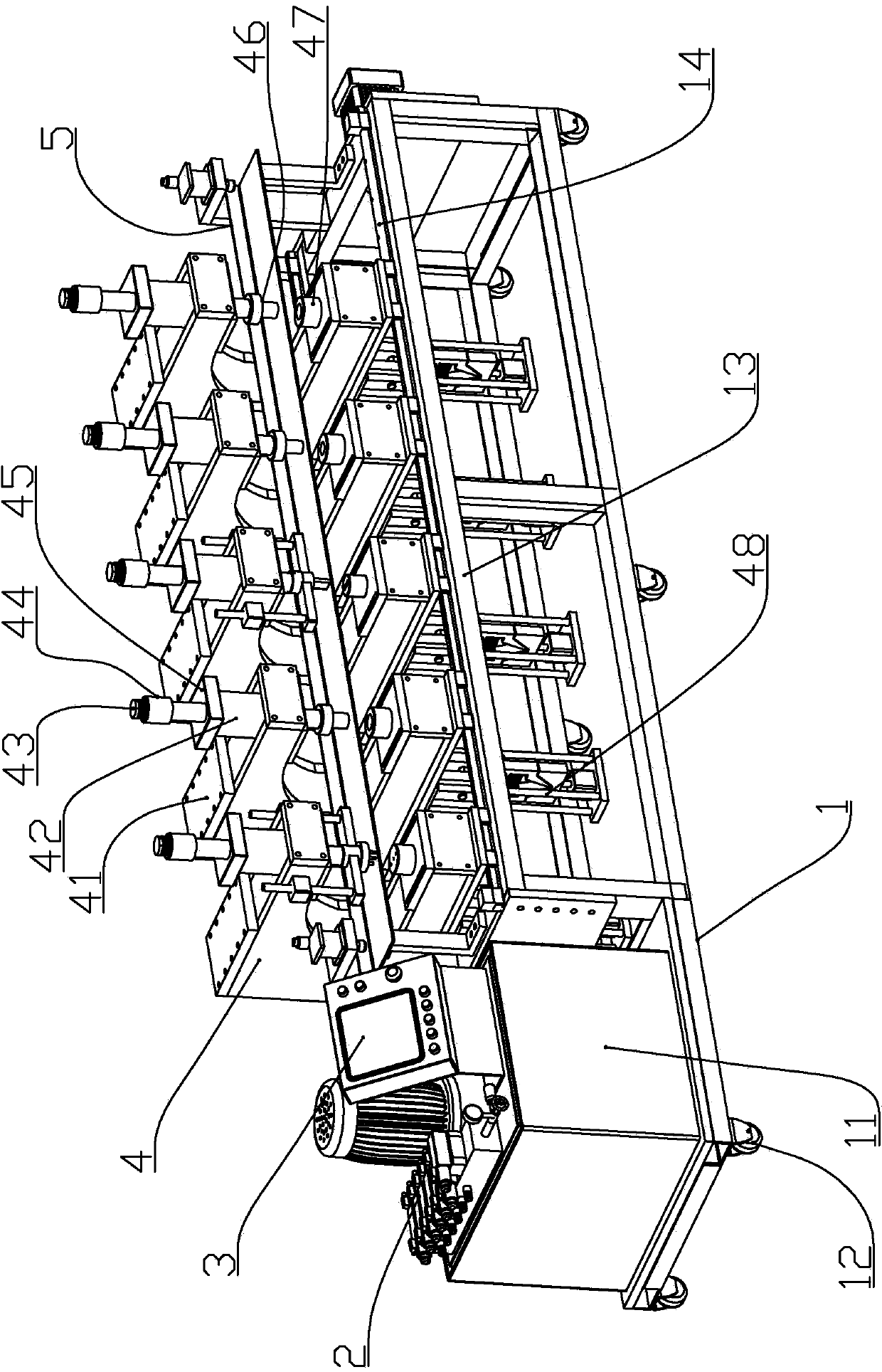
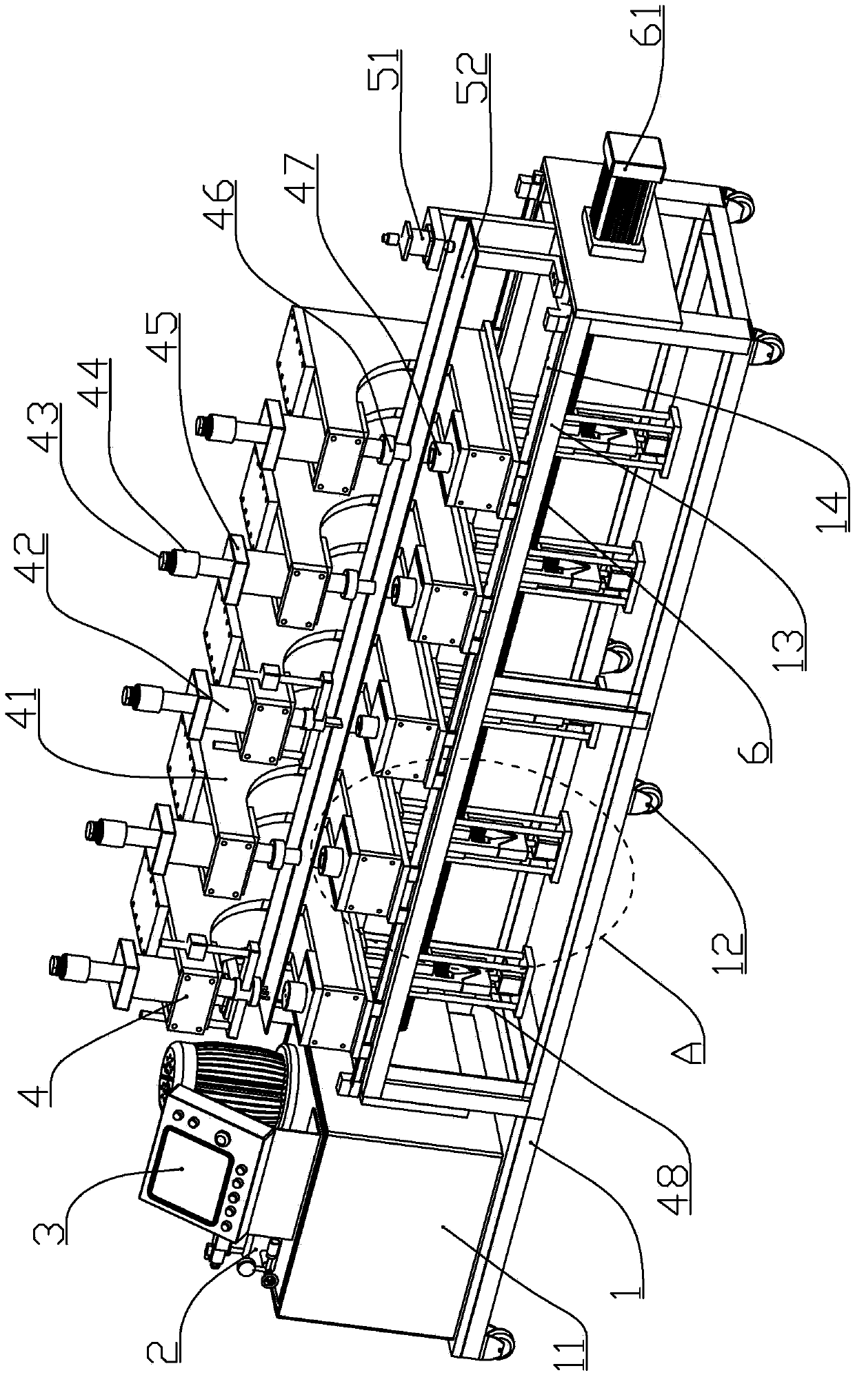
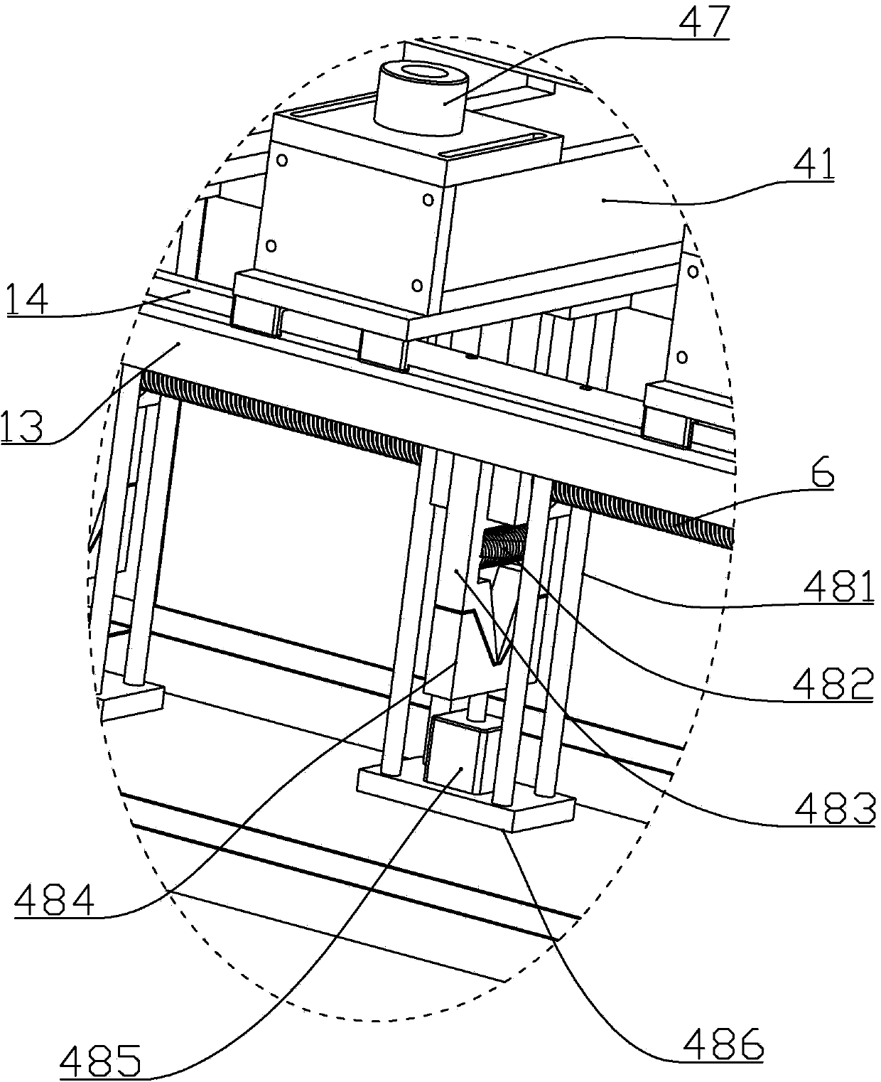
[0017] according to Figure 1 to Figure 5 As shown, a kind of stamping equipment described in this embodiment includes a chassis 1, a punch bracket 13 welded on the bottom chassis, two parallel guide rails 14 arranged along the length direction above the punch bracket, and A plurality of punch presses 4 installed above the guide rail; the punch press includes a C-shaped punch frame 41 as a whole, a double-piston rod hydraulic cylinder 42 vertically installed on the upper part of the punch frame, fixedly mounted on the hydraulic cylinder piston The upper mold 46 at the lower end of the rod, and the lower mold 47 fixedly installed on the lower part of the punch frame and matched with the upper mold; the upper end of the piston rod of the hydraulic cylinder is threadedly connected with an adjusting nut 44, and the upper part of the hydraulic...


PUM


Abstract

The invention discloses a stamping device. The stamping device comprises a bottom frame, a punch press support, two parallel guide rails and a plurality of punch presses, wherein the punch press support is welded to the position above the bottom frame, the guide rails are installed on the punch press support in the length direction, and the punch presses are installed above the guide rails. Each punch press comprises an integral C-shaped punch press rack, a hydraulic cylinder vertically installed at the upper portion of the punch press rack, an upper die fixedly installed at the lower end of a hydraulic cylinder piston rod, and a lower die fixedly installed at the lower portion of the punch press rack. A transmission lead screw is arranged on the punch press support in the length direction, a punch press transverse movement device is fixedly connected to the lower portion of the punch press rack, same or different types of stamping dies can be installed on the different punch presses, the punch presses are moved to positions to be punched through the punch press transverse movement device, all workpieces to be punched are clamped and fixed through a workpiece clamp, the punch presses can act at the same time to punch the workpieces to form a plurality of holes, machining efficiency is high, and punching time is greatly shortened.

Description

technical field [0001] The invention belongs to the field of punching machine structures, and in particular relates to a punching device capable of simultaneously or continuously punching a plurality of through holes with different shapes. Background technique [0002] Existing stamping machine tools punch each hole separately when punching the plate, while the turret-type punching machine can be equipped with multiple molds, which can realize continuous punching of multiple holes of various specifications on the same plate. holes, but after punching a hole, the mold has to move one or several stations, the process of mold transposition takes a lot of time, and the overall stamping efficiency is still low. Especially unfavorable for the processing of large quantities of plates. Contents of the invention [0003] The technical problem to be solved by the present invention is to provide a stamping equipment with compact structure and high stamping efficiency in view...

Claims


Application Information

Patent Timeline
Patent Type & Authority Applications(China)
IPC IPC(8): B21D28/26
Inventor 钟燕浩张树前朱建军
Owner ZHEJIANG ZHONGGUANG ELECTRIC CO LTD
Why Eureka
Try Eureka