Full-automatic flame cutting device

A flame cutting and cutting device technology, applied in auxiliary devices, gas flame welding equipment, welding/cutting auxiliary equipment, etc., can solve the problems of high labor cost, high labor intensity, low efficiency, etc., and achieve low cost and high work efficiency. , the effect of reducing friction

Active Publication Date: 2014-12-10
NANJING CHEM CONSTR
View PDF7 Cites 3 Cited by
  • Summary
  • Abstract
  • Description
  • Claims
  • Application Information

AI Technical Summary

Problems solved by technology

[0002] At the construction site of a large storage tank, the positioning device needs to be welded to the storage tank when the storage tank is docked and positioned. Generally, in order to save costs, the material of the positioning device is different from that of the storage tank. At this time, the same material as the storage tank is required. The middle bridge is welded on the storage tank at one end and on the p

Method used


Image

  • Full-automatic flame cutting device
  • Full-automatic flame cutting device
  • Full-automatic flame cutting device

Examples


Embodiment 1

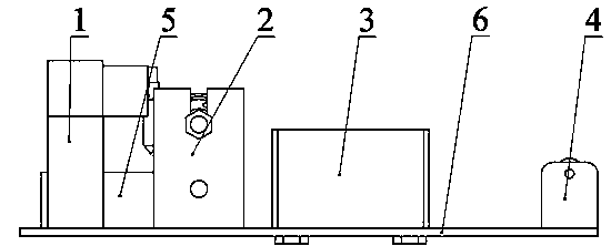
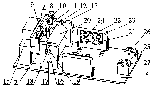
[0026] Example 1: Such as figure 1 , figure 2 , Figure 5 , Figure 8 , a fully automatic flame cutting device, the fully automatic flame cutting device includes a cutting device 1, a longitudinal pressing device 2, a lateral limiting device 3, a support wheel device 4, a finished product collection box 5 and a device bottom plate 6, the described The cutting device 1 is installed on one end of the device base plate 6 by welding, and the longitudinal pressing device 2 is installed on the device base plate 6 by welding, and a finished product collection box 5 is arranged between the cutting device 1 and the longitudinal pressing device 2, so that The lateral limiting device 3 is installed on the bottom plate 6 of the device through a limit adjusting screw 35, and the supporting wheel device is installed on the other end of the bottom plate of the device. In this technical solution, the cutting device 1 is used for flame cutting the plate 38, the longitudinal pressing devi...

Embodiment 2

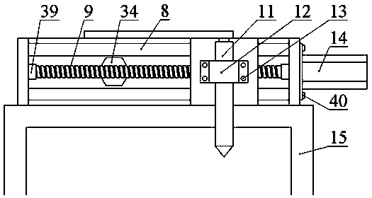
[0027] Example 2: Such as figure 1 , figure 2 , image 3 , Figure 5, as an improvement of the present invention, the cutting device 1 includes a cutting device mounting frame 7, a cutting device support frame 15, a sliding rod 8, a lead screw 9, a sliding block 10, a linkage device 39, a small servo motor 14, a small servo Motor screw 40 and screw rod 34, described cutting device support frame 15 is installed on the front end position of device bottom plate by welding, and described cutting device mounting frame 7 is installed on the cutting device support frame 15 by screw rod 34, and described slide bar 8 is threaded Installed on the cutting device mounting frame, one end of the leading screw 9 is installed on the cutting device mounting frame through a linkage 39, and the other end is connected to a small servo motor 14, and the small servo motor 14 is installed on the cutting device through a small servo motor screw 40. The right end of the mounting frame 7, the sli...

Embodiment 3

[0028] Example 3: Such as figure 1 , image 3 , as an improvement of the present invention, the linkage device 39 is set as a rolling bearing or other bearing structure. The rest of the structures and advantages are exactly the same as in Embodiment 1.


PUM


Abstract

The invention relates to a full-automatic flame cutting device. The full-automatic flame cutting device is characterized in that the full-automatic flame cutting device comprises a cutting unit (1), a longitudinal compressing device (2), a transverse limiting device (3), a supporting wheel device (4), a finished product collecting box (5) and a device bottom plate (6), the cutting unit (1) is installed at one end of the device bottom plate in a welded mode, the longitudinal compressing device is installed on the device bottom plate in a welded mode, the finished product collecting box (5) is arranged between the cutting unit and the longitudinal compressing device (2), the transverse limiting device is installed on the device bottom plate through a limiting adjusting screw, and the supporting wheel device is installed at the other end of the device bottom plate.

Description

technical field [0001] The invention relates to a cutting device, in particular to a fully automatic flame cutting device, which belongs to the technical field of sheet metal cutting. Background technique [0002] At the construction site of a large storage tank, the positioning device needs to be welded to the storage tank when the storage tank is docked and positioned. Generally, in order to save costs, the material of the positioning device is different from that of the storage tank. At this time, the same material as the storage tank is required. The middle bridge is welded on the storage tank at one end and on the positioning device at the other end. Similarly, when scaffolding is built inside the storage tank, pads with the same material as the storage tank are also required as intermediate connectors. Since the plates are cut into pieces, At the site, these pads are measured manually on the plate, marked, and then manually cut with a flame gun, but the efficiency is l...

Claims


Application Information

Patent Timeline
IPC IPC(8): B23K7/00B23K7/10
CPCB23K7/002B23K7/10B23K37/0408B23K2101/18
Inventor 李少宁冯启胜邓金红陈建栋
Owner NANJING CHEM CONSTR
Why Eureka
Try Eureka