Device for shifting rapid transfer trolley wheels of transverse marshalling rack

A technology of shifting device and marshalling table, which is applied in the direction of conveyor, mechanical conveyor, transportation and packaging, etc. It can solve the problem of affecting the normal production rhythm of the rolling line, the service life of equipment, the high failure rate of rolling equipment, and the tipping of trolleys. and other problems, to achieve the effect of solving the problem of trolley overturning, convenient disassembly, assembly, maintenance and replacement, and low cost

Inactive Publication Date: 2015-01-28
JIANGSU LIANFENG ENERGY EQUIP
View PDF6 Cites 0 Cited by
  • Summary
  • Abstract
  • Description
  • Claims
  • Application Information

AI Technical Summary

Problems solved by technology

When the trolley is used to transport large-sized rolled parts, due to the existence of the cantilever, the force arm of the trolley is likely to be greater than the arm of the tilting force, which will cause the trolley to

Method used


Image

  • Device for shifting rapid transfer trolley wheels of transverse marshalling rack
  • Device for shifting rapid transfer trolley wheels of transverse marshalling rack
  • Device for shifting rapid transfer trolley wheels of transverse marshalling rack

Examples


Embodiment 1

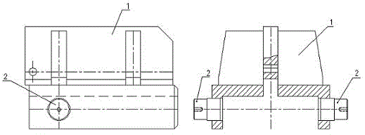
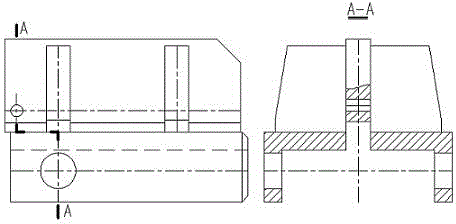
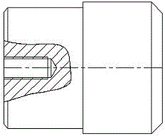
[0016] Embodiment 1: as figure 1 — image 3 , the wheel shifting device for the rapid transfer trolley of the traversing marshalling platform, including an extended support 1, a support roller shaft 2, and a fast transfer trolley wheel, the extended support 1 is fixedly connected with the support roller shaft 2, and the support roller shaft 2 Mounted on quick shift trolley wheels. The design of the whole technical scheme is ingenious and practical, which not only solves the problem of trolley overturning during steel production, but also reduces the failure rate of equipment.

Embodiment 2

[0017] Embodiment 2: as figure 1 — image 3 , as an improvement of the present invention, the number of the support roller shafts 2 is two. The wheel shifting device is mainly used for shifting the trolley wheels below the cantilever end, and the number of trolley wheels below the cantilever is 2, so the number of the support roller shafts is consistent with it. The rest of the structures and advantages are exactly the same as in Embodiment 1.

Embodiment 3

[0018] Embodiment 3: as figure 1 — image 3 , as an improvement of the present invention, when installing the extension bracket 1 and the bracket roller shaft 2, it is necessary to ensure that the concentricity of the two bracket roller shafts 2 is consistent. This can reduce the breakage phenomenon of the support roller shaft 2, thereby ensuring a longer service life of the wheel displacement device. The rest of the structures and advantages are exactly the same as in Embodiment 1.


PUM


Abstract

The invention relates to a device for shifting rapid transfer trolley wheels of a transverse marshalling rack. The wheel shifting device comprises a lengthened bracket, two bracket roller shafts and the rapid shifting trolley wheels; the device is arranged at the front end of a rapid transfer trolley of a large rod transverse marshalling rack and fixed with a rapid transfer trolley body via welding; when the lengthened bracket and the bracket roller shafts are mounted, the concentricity of the two bracket roller shafts needs to be ensured and the connection end faces of the bracket roller shafts and the lengthened bracket are not damaged in the welding process. The device adopts a combined structure, and the two trolley wheels below a cantilever end of an original transverse marshalling rack is moved forwards to change the gravity of the whole equipment, so that the gravity of an original overhanging mechanism and an original rotation center are located on a same straight line, the trolley tipping problem during the transportation of large-scale round steels or square blanks in the production process is solved, the productivity is improved and the failure frequency of the equipment is reduced.

Description

[0001] technical field [0002] The invention relates to a wheel shifting device for a transfer trolley on a bar rolling marshalling stand, and belongs to the technical field of large-scale special steel rolling equipment. Background technique [0003] The traverse marshalling stand is one of the more important steel rolling auxiliary equipment in the large-scale bar rolling production, which plays the role of adjusting the production rhythm and connecting the past and the future. The traversing marshalling stand is mainly composed of an input roller table, a feeding plate, a collection table, a transfer trolley and an output roller table. The round steel or square billet produced by the continuous bar rolling mill needs to be transported to the output roller table by the transfer trolley. Due to the complex structure below the input roller table, the transfer trolley in the prior art mostly adopts the cantilever structure, and the transfer trolley has 4 stations, 2 of which...

Claims


Application Information

Patent Timeline
IPC IPC(8): B65G35/00
Inventor 李雄李彦林顾俊杰冯大圣马伟武东国
Owner JIANGSU LIANFENG ENERGY EQUIP
Why Eureka
Try Eureka