Multi-layer decoration injection mold

A technology for injection molds and concave molds, which is applied in the field of multi-layer decorative injection molds and mold parts. It can solve the problems of complex production process of injection molds, stuck injection products, and long production cycle, so as to ensure the quality and stability of extruded products. Sexuality and high work efficiency

Inactive Publication Date: 2017-05-31
南京汉安科技实业有限公司
View PDF3 Cites 0 Cited by
  • Summary
  • Abstract
  • Description
  • Claims
  • Application Information

AI Technical Summary

Problems solved by technology

Some injection molded products have reinforcing ribs. Due to the shrinkage of plastic materials, injection products are often stuck on the thimble, and there are also the following problems, such as low working life, high scrap rate, comple

Method used


Image

  • Multi-layer decoration injection mold

Examples


Embodiment 1

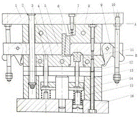
[0015] Embodiment 1: see figure 1 , a multi-layer decorative injection mold, the injection mold includes an upper mold 5, an upper mold bottom plate 1, a lower mold 4, a lower mold bottom plate 16, a feeding chamber 8, a multilayer backing plate 12, a die 11, a push assembly and a fixed From the pull rod 2, the feeding chamber 8 is arranged between the bottom plate of the upper mold and the upper mold, the multi-layer backing plate is arranged between the bottom plate of the lower mold and the lower mold, the pushing assembly is arranged on the bottom plate of the lower mold, and the concave mold 11 is arranged on the multi-layer backing plate, and the distance tie rod is used to position the multi-layer backing plate and the upper mold of the upper mold; the injection mold also includes a sprue sleeve 6 and a pressure column 7, and the sprue sleeve is set On the upper mold, the pressure column is arranged on the bottom plate of the upper mold, the thickness of the multi-layer...

Embodiment 2

[0016] Example 2: see figure 1 , as an improvement of the present invention, the injection mold also includes a pull hook 9, and the pull hook 9 is arranged on the upper mold 5, and the injection mold also includes a pull rod 10, and the pull rod 10 is arranged on the bottom plate of the upper mold, so The number of said pull rods is two. The rest of the structures and advantages are exactly the same as in Embodiment 1.

Embodiment 3

[0017] Embodiment 3: see figure 1 , as an improvement of the present invention, the push assembly further includes a push rod 13, a push plate 14 and a spring 15, the push rod is set on the push plate, and the push plate is set on the spring. The rest of the structures and advantages are exactly the same as in Embodiment 1.

[0018] Work process: see figure 1 , when working, install the mold on an upper-press type press for use. When the mold is opened, the press drives the bottom plate 1 of the upper mold to rise, that is, the mold is divided from the A surface, so that the pressure column 7 leaves the feeding chamber with the main channel condensate , when the bottom plate of the upper mold is opened for a distance S, the nut on the pull rod 10 contacts with the pull hook 9 fixed on the upper template 5 and can rotate around the axis, so that the pull hook is disengaged from the lower mold 4. At this time, due to the fixed distance pull rod 2 Pull the upper mold 5 to make ...


PUM

PropertyMeasurementUnit
Thicknessaaaaaaaaaa

Abstract

The invention relates to a multi-layer decoration injection mold. The injection mold comprises an upper mold body, an upper mold bottom plate, a lower mold body, a lower mold bottom plate, a charging chamber, a multi-layer cushion plate, a female mold body, a push assembly and fixed-distance pull rods. The charging chamber is arranged between the upper mold bottom plate and the upper mold body. The multi-layer cushion plate is arranged between the lower mold bottom plate and the lower mold body. The push assembly is arranged on the lower mold bottom plate. The female mold body is arranged on the multi-layer cushion plate. The fixed-distance pull rods position the multi-layer cushion plate of the upper mold body and the upper mold body. The thickness of the multi-layer cushion plate ranges from 10 CM to 50 CM. The device is ingenious and compact in overall structural design and low in cost. According to the technical scheme, the product precision can be well guaranteed, the work efficiency is high, the production period is short, and the enterprise cost is reduced.

Description

technical field [0001] The invention relates to a mold, in particular to a multi-layer decorative injection mold, which belongs to the technical field of mold parts. Background technique [0002] Mold, various molds and tools used in industrial production for injection molding, blow molding, extrusion, die-casting or forging forming, smelting, stamping and other methods to obtain the required products. In short, a mold is a tool used to shape an object. This tool is composed of various parts, and different molds are composed of different parts. It mainly realizes the processing of the shape of the article through the change of the physical state of the formed material. Under the action of external force, the blank becomes a tool with a specific shape and size. Widely used in blanking, die forging, cold heading, extrusion, powder metallurgy parts pressing, pressure casting, and compression molding or injection molding of engineering plastics, rubber, ceramics and other prod...

Claims


Application Information

Patent Timeline
IPC IPC(8): B29C45/26B29C45/40
CPCB29C45/26B29C45/2606B29C45/4005
Inventor 钮承杰
Owner 南京汉安科技实业有限公司
Why Eureka
Try Eureka