

Automatic hand disinfection device
A hand disinfection and automatic technology, applied in the direction of disinfection, water supply equipment, sanitary equipment for toilets, etc., can solve the problems of manual disinfection service work intensity, manual disinfection is not in place, disinfection has dead corners and omissions, etc., to achieve easy operation and Popularity, ingenious overall structure design, and good versatility
- Summary
- Abstract
- Description
- Claims
- Application Information
AI Technical Summary
Problems solved by technology
Method used
Image

Examples
Embodiment 1
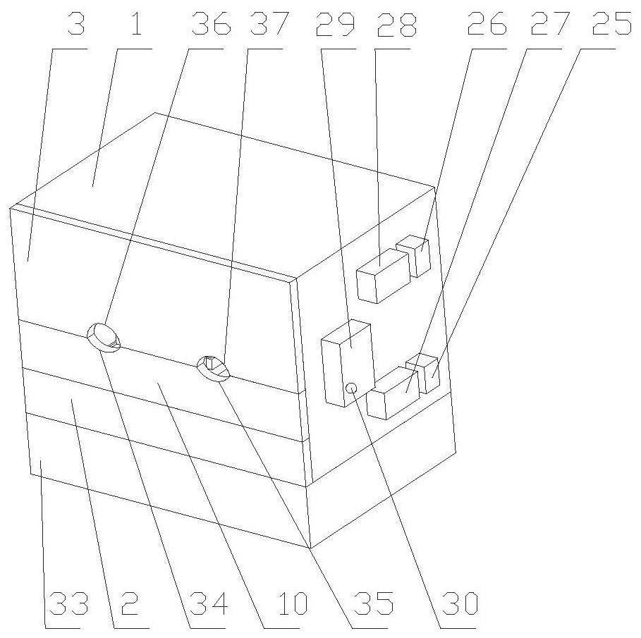
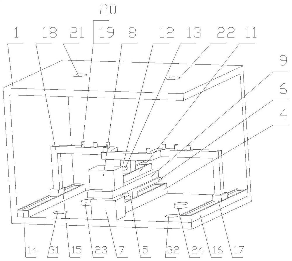
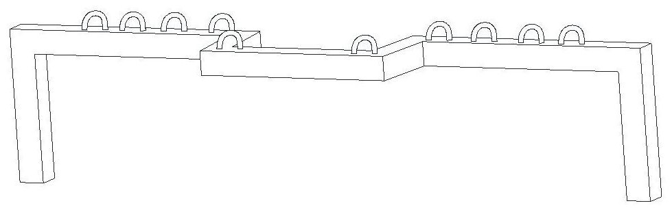
[0017]The main structure of the automatic hand disinfection device involved in this embodiment includes: a disinfection cover 1, a first front baffle 2, a second front baffle 3, a first track 4, a first slider 5, and a first screw 6 , the first motor 7, the second motor 8, the moving plate 9, the front baffle plate 10 of the moving plate, the second track 11, the second slider 12, the second lead screw 13, the third track 14, the third slider 15, the second Four track 16, fourth slide block 17, finger support 18, sub-finger block 19, sensor 20, first upper nozzle 21, second upper nozzle 22, first lower nozzle 23, second lower nozzle 24, first liquid storage Device 25, second liquid reservoir 26, first piston pump 27, second piston pump 28, controller 29, start switch 30, first waste liquid outlet 31, second waste liquid outlet 32 and waste liquid storage 33; Disinfection cover 1 is a cubic shell structure, its wall thickness is 2~5mm, length is 380~460mm, width is 200~320mm,...
Embodiment 2
[0021] The main structure of the automatic hand disinfection device involved in this embodiment is the same as that of Embodiment 1. The first rail 4 in the center of the disinfection cover 1 is vertically provided with isolation baffles on both sides, and the electrical and electronic components in the center of the disinfection cover 1 The mobile structure is isolated, which is not only beautiful, but also plays a protective role. A long horizontal hole is arranged on the isolation baffle for the reciprocating movement of the finger support 18.
Embodiment 3
[0023] The main structure of the automatic hand disinfection device involved in this embodiment is the same as that in Embodiment 1 or 2. The finger-pointing block 19 is an arched cylindrical ring, and the number of arched cylindrical rings is ten, which is used for wearing ten fingers. However, prevent the fingers from moving outwards.
[0024] Further, a sponge is attached to the inner surface of the disinfection cover 1 and the outer surface of the isolation baffle vertically arranged on both sides of the first track 4. The thickness of the sponge is 2-6mm, which is convenient for absorbing the sprayed disinfectant, and the sponge is replaced manually at regular intervals. .
PUM
| Property | Measurement | Unit |
|---|---|---|
| Wall thickness | aaaaa | aaaaa |
| Thickness | aaaaa | aaaaa |
Abstract
Description
Claims
Application Information