
Die head applied to blow moulding machine

A blow molding machine and die head technology, which is applied to the die head field of blow molding machines, can solve the problems of uneven thickness of containers, inability to make transparent lines, complicated processes of transparent lines, etc., and achieve the effect of avoiding uneven distribution.

Inactive Publication Date: 2014-12-10
ZHANGJIAGANG PUXIN MACHINERY
View PDF5 Cites 0 Cited by
  • Summary
  • Abstract
  • Description
  • Claims
  • Application Information

AI Technical Summary

Problems solved by technology

[0004] Traditional extrusion blow molding machines usually have the following problems: 1. Only single-layer containers can be produced; 2. The thickness of the produced containers is uneven; 3. It is impossible to make transparent lines or the process of making transparent lines is complicated

Method used


Image

  • Die head applied to blow moulding machine
  • Die head applied to blow moulding machine
  • Die head applied to blow moulding machine

Examples


Embodiment Construction

[0028] The technical solutions in the embodiments of the present invention will be described in detail below in conjunction with the accompanying drawings in the embodiments of the present invention. Obviously, the described embodiments are only some of the embodiments of the present invention, not all of them. Based on the embodiments of the present invention, all other embodiments obtained by persons of ordinary skill in the art without making creative efforts belong to the protection scope of the present invention.

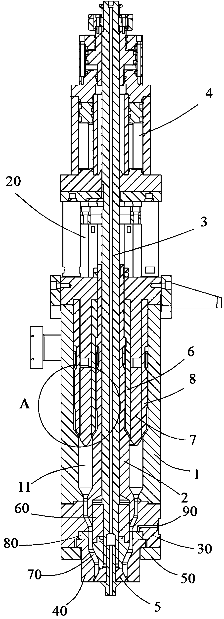
[0029] ginseng figure 1 As shown, the blow molding machine die head includes a storage barrel 1, and the storage barrel 1 has a cavity with an open bottom.

[0030] A storage core 2 is arranged in the cavity of the storage tube 1 along the axial direction, and the top end of the storage core 2 is fixed on the storage tube 1 . An annular actuating space and an annular storage space 11 are enclosed between the storage core 2 and the inner wall of the storage bar...


PUM


Abstract

The invention discloses a die head applied to a blow moulding machine. The die head applied to the blow moulding machine comprises a material storage cylinder, wherein a material storage core is arranged in a cavity of the material storage cylinder in an axis direction; a material injection piston and an outer layer sleeve are sequentially arranged on the outer side of the material storage core in a sleeving manner; a second runner space is formed between the outer layer sleeve and the inner wall of the material storage cylinder; the bottom end of the second runner space is communicated to a material storage space; the surface of the outer layer sleeve is sunken to form runners; the runners are communicated with a second feeding hole; the runners comprise a runner I, a runner II, a runner III, a runner IV, a runner V, a runner VI and a runner VII; the runner I is wound along the axis; the runner II and the runner III symmetrically extend downwards from the two ends of the runner I; the runner II is divided downwards into two branches, namely the runner IV and the runner V; the runner III is divided downwards into two branches, namely the runner VI and the runner VII; the tail end of the runner IV is communicated with the tail end of the runner VI; the tail end of the runner V is communicated with the tail end of the runner VII. According to the die head applied to the blow moulding machine, the surface of the outer layer sleeve is sunken to form the runners; the runners are divided by a manner of dividing one into two and then dividing two into four, so that fluid can uniformly flow downwards around a column body I, and thus the phenomenon of uneven distribution in a partial region is avoided.

Description

technical field [0001] The invention belongs to the field of hollow blow molding, in particular to a die head for a blow molding machine. Background technique [0002] Blow molding (blow molding), also known as hollow blow molding, is a rapidly developing plastic processing method. The tubular plastic parison obtained by extrusion or injection molding of thermoplastic resin is placed in the split mold while it is hot (or heated to a softened state), and compressed air is injected into the parison immediately after the mold is closed to blow the plastic parison. It swells and clings to the inner wall of the mold, and after cooling and demoulding, various hollow products can be obtained. [0003] Extrusion blow molding machine is a combination of extruder, blow molding machine and mold clamping mechanism. It is composed of extruder, parison die head, inflation device, mold clamping mechanism, parison thickness control system and transmission mechanism. The parison die is one...

Claims


Application Information

Patent Timeline
Patent Type & Authority Applications(China)
IPC IPC(8): B29C49/48B29C49/42B29C49/04
Inventor 杨德刚陆胜钱伟
Owner ZHANGJIAGANG PUXIN MACHINERY
Learn More