Quick connection and positioning structure for assembly of offshore buoyancy tanks

A technology for quick connection and positioning of the structure, applied in the direction of floating buildings, etc., can solve the problems of heavy weight, manpower and material resources, large joint volume, etc., and achieve the effect of light weight, cost saving and low investment cost

Active Publication Date: 2016-08-10
TIANJIN TDBH NAVAL ARCHITECTURE & OCEAN ENG ACADEMY
View PDF7 Cites 2 Cited by
  • Summary
  • Abstract
  • Description
  • Claims
  • Application Information

AI Technical Summary

Problems solved by technology

[0002] At present, offshore buoyant tanks are formed by assembling multiple modules, and joints are used to connect adjacent buoyant tank modules. The following problems generally exist in the offshore assembly process of buoyant tank modules: 1) During the docking process of offshore buoyant tanks, there is a slight Affected by wind and waves, it is difficult for the joints to accurately align or enter the connection box seat of the buoyancy tank to be connected. The operability of the joint connection is not high, and it is difficult to connect the joints; 2) The joints are large in size and heavy in weight, and cannot be assembled by manpower Operation requires the use of power equipment for traction. When assembling buoys at sea, the force of power equipment traction needs to be suitable for the floating of the buoys. Damaged by collision of pontoons
In short, during the assembly process of offshore floating tanks, due to the lack of stable positioning of the relative positions between two adjacent floating tank modules, the joint connection operation is very difficult, which consumes a lot of time, manpower and material resources

Method used


Image

  • Quick connection and positioning structure for assembly of offshore buoyancy tanks
  • Quick connection and positioning structure for assembly of offshore buoyancy tanks
  • Quick connection and positioning structure for assembly of offshore buoyancy tanks

Examples


Embodiment Construction

[0016] In order to further understand the invention content, characteristics and effects of the present invention, the following examples are given, and detailed descriptions are as follows in conjunction with the accompanying drawings:

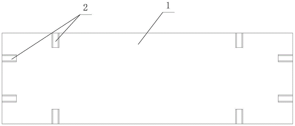
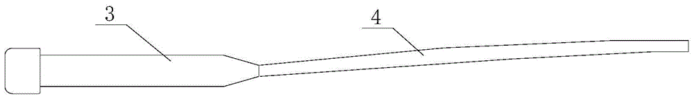
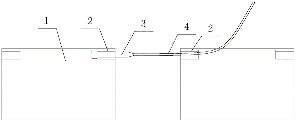
[0017] see Figure 1 ~ Figure 4 , a quick connection and positioning structure for assembly of offshore buoyancy tanks, comprising a connection positioning seat 2 and a connection positioning component arranged on a buoyancy tank module 1 .

[0018] Corresponding to each connection surface of the buoyancy tank module 1, at least two connection positioning seats 2 are installed, and a pin hole perpendicular to the connection surface is provided in the connection positioning seat 2 . In this embodiment, in order to facilitate the formation of pin holes, the connecting positioning seat adopts a tubular structure, usually a round tube or a square tube. The position of the connection positioning seat 2 in the vertical direction is near the deck s...


PUM


Abstract

The invention discloses a quick connecting positioning structure for assembling offshore buoyancy tanks. The quick connecting positioning structure comprises connecting positioning seats and connecting positioning components. The connecting positioning seats are arranged on buoyancy tank modules; at least two connecting positioning seats are mounted on each connecting surface of the corresponding buoyancy tank module, and hinge pin holes which are perpendicular to the connecting surfaces are formed in the connecting positioning seats; the connecting positioning components are provided with hinge pins and flexible ropes, and the flexible ropes are connected with the hinge pins; each connecting positioning component is penetratingly arranged in the hinge pin holes of the two corresponding connecting positioning seats which are opposite to the two corresponding to-be-assembled buoyancy tank modules, and each two corresponding buoyancy tank modules are connected with each other by the corresponding connecting positioning components to be close to each other. The quick connecting positioning structure has the advantages that each two corresponding to-be-assembled buoyancy tank modules can quickly move to assembling connecting positions and can keep stable at the relative positions; connectors can be conveniently connected with one another after the buoyancy tank modules are connected and positioned, and the buoyancy tank modules can be integrally connected with one another by the connectors.

Description

technical field [0001] The invention relates to a connection and positioning structure, in particular to a quick connection and positioning structure for assembling floating tanks on the sea. Background technique [0002] At present, offshore buoyant tanks are formed by assembling multiple modules, and joints are used to connect adjacent buoyant tank modules. The following problems generally exist in the offshore assembly process of buoyant tank modules: 1) During the docking process of offshore buoyant tanks, there is a slight Affected by wind and waves, it is difficult for the joints to accurately align or enter the connection box seat of the buoyancy tank to be connected. The operability of the joint connection is not high, and it is difficult to connect the joints; 2) The joints are large in size and heavy in weight, and cannot be assembled by manpower Operation requires the use of power equipment for traction. When assembling buoys at sea, the force of power equipment t...

Claims


Application Information

Patent Timeline
Patent Type & Authority Patents(China)
IPC IPC(8): B63B35/44
Inventor 谷峰孙桢
Owner TIANJIN TDBH NAVAL ARCHITECTURE & OCEAN ENG ACADEMY
Why Eureka
Try Eureka