
Automatic cutting and unwinding equipment

A kind of unwinding equipment and cutting technology, which is applied in the directions of sending objects, thin material handling, transportation and packaging, etc., can solve the problems of scrap, waste and uneven cutting surface of the coil.

Inactive Publication Date: 2014-12-10
孟昊
View PDF7 Cites 3 Cited by
  • Summary
  • Abstract
  • Description
  • Claims
  • Application Information

AI Technical Summary

Problems solved by technology

[0002] The cutting part of the existing unwinding unit uses a cutter (generally the cutter is zigzag) for cutting, and the cutting method of the cutter is vertically downward from top to bottom, but it is limited by Influenced by the coil tension on the left and right sides of the cutting part, the cutting surface is uneven, and a certain length of the coil will be scrapped, resulting in waste

Method used


Image

  • Automatic cutting and unwinding equipment
  • Automatic cutting and unwinding equipment
  • Automatic cutting and unwinding equipment

Examples


Embodiment Construction

[0017] The present invention will be further described in detail below in conjunction with the drawings.

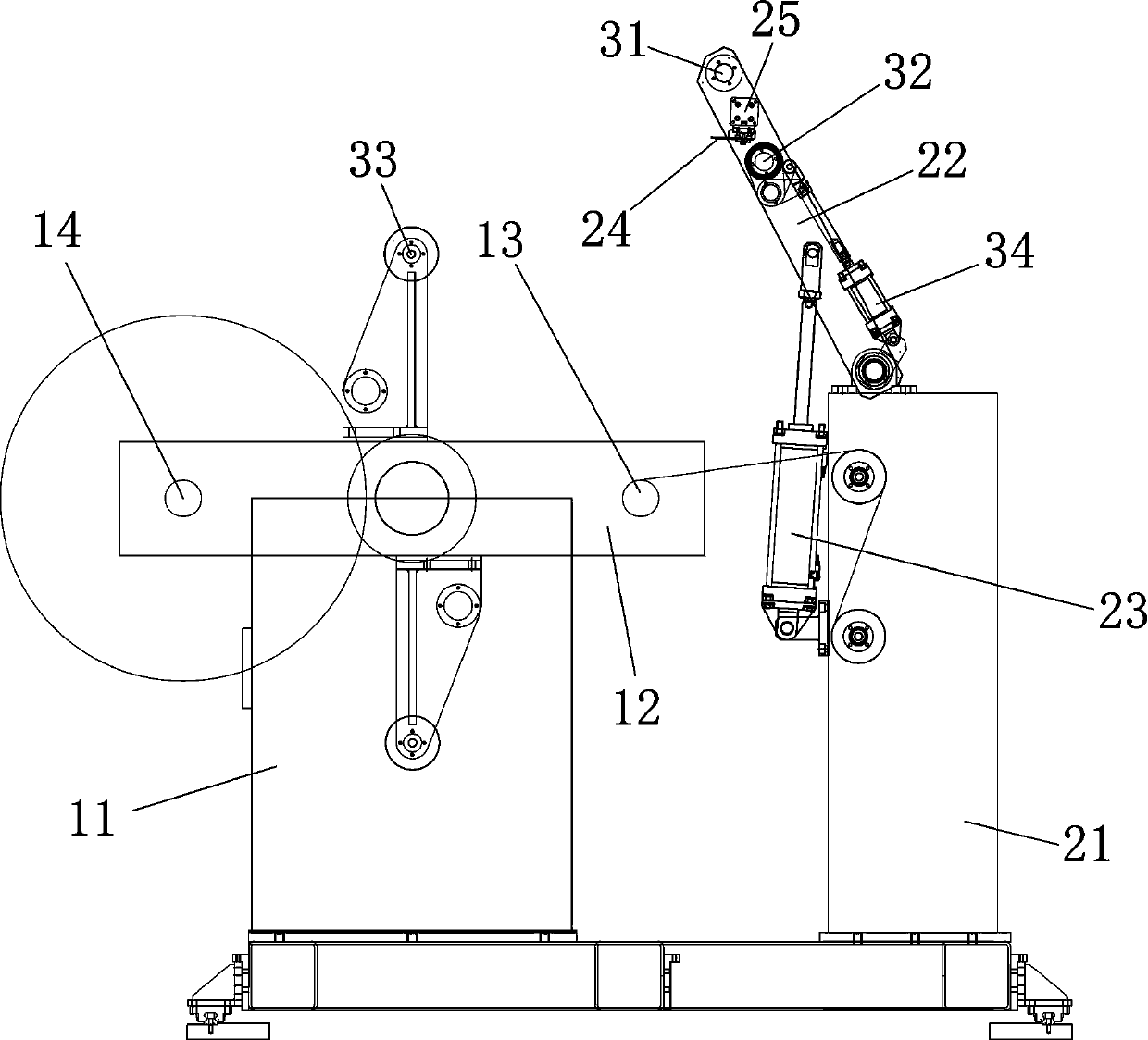
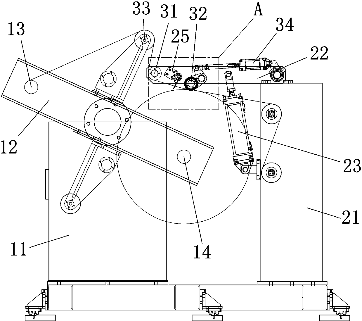
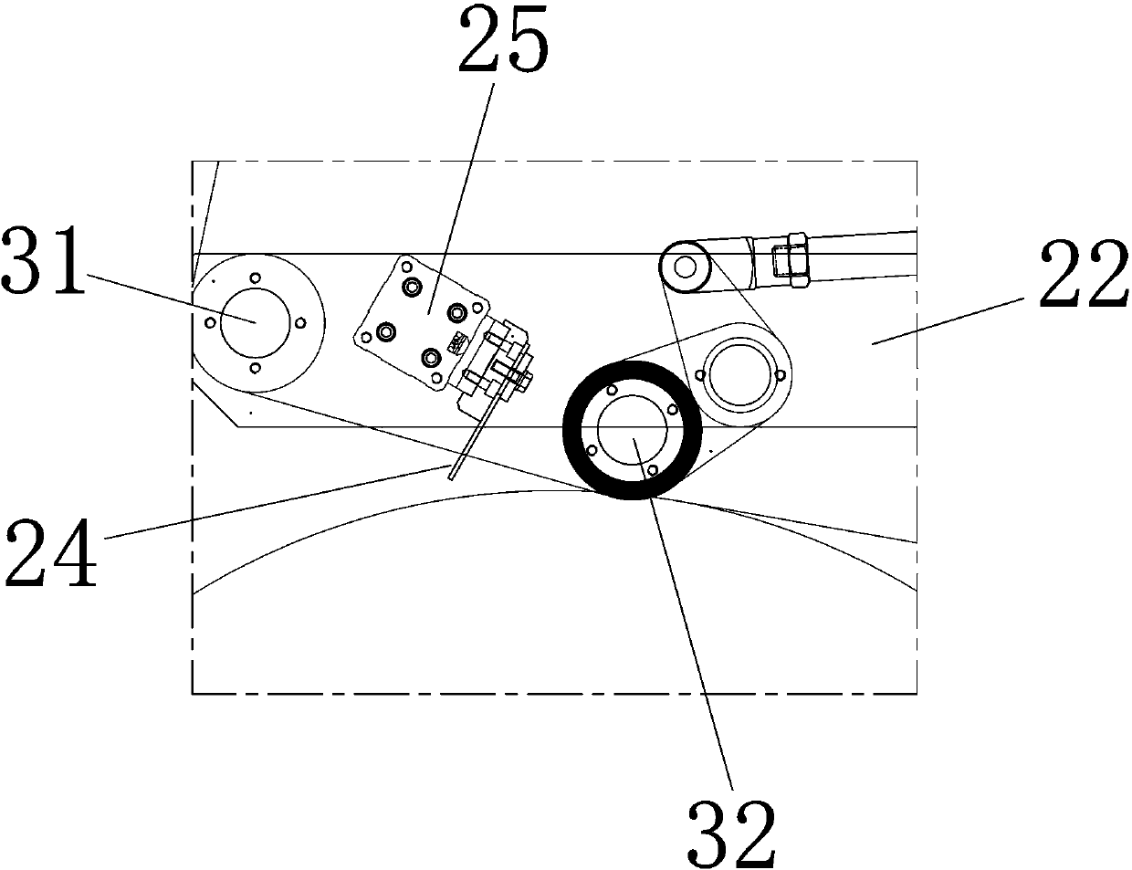
[0018] Such as figure 1 , 2 As shown in 3, an automatic cutting and unwinding device includes a frame and an unwinding mechanism, a tensioning mechanism and a cutting mechanism installed on the frame.

[0019] The unwinding mechanism includes an unwinding support frame 11, a reel mounting frame 12 and a reel. The unwinding support frame 11 is fixed on the frame, and the middle part of the reel mounting frame 12 is hinged to the unwinding support frame 11. The reel mounting frame 12 is made to rotate, and both ends of the reel mounting frame 12 are respectively provided with a reel, and the reel is used for unwinding; the reel can also be rotated by the power device. The reel that is about to be unrolled is used as the old reel 14, and the reel provided with a new coil is used as the new reel 13. When the old reel 14 is finished unwinding, the reel needs to be replaced to make ...


PUM


Abstract

The invention discloses automatic cutting and unwinding equipment. The automatic cutting and unwinding equipment comprises an unwinding mechanism, a tensioning mechanism and a cutting mechanism. The unwinding mechanism comprises at least two winding drums, wherein the winding drum completing unwinding is an old-coil winding drum, and the winding drum provided with coiled materials is a new-coil winding drum. The tensioning mechanism comprises a compression roller device and a first bypass roller device. The cutting mechanism comprises a cutter and a cutter drive device. The cutter is arranged between the compression roller device and the first bypass roller device. When the cutting mechanism performs cutting, the unwinding mechanism rotates to make the new-coil winding drum be located at the unwinding position, the coiled materials between the new-coil winding drum and the old-coil winding drum are pressed by the first bypass roller device so that the coiled materials can be tightened, and the coiled materials on the old-coil winding drum are compressed and fixed to the coiled materials of the new-coil winding drum through the compression roller device. The cutter is controlled by the cutter drive device to transversely cut the coiled materials between the first bypass roller device and the new-coil winding drum.

Description

Technical field [0001] The invention relates to the technical field of coating machine equipment, in particular to an automatic cutting and unwinding equipment. Background technique [0002] The cutting part of the existing unwinding unit uses a cutter (generally cutters are zigzag type) for cutting, and the cutting method of the cutter is to cut from top to bottom vertically, but it is affected by The influence of the coil tension on the left and right sides of the cutting part causes uneven cutting surface, and will cause a certain length of coil to be scrapped, thereby causing waste. Summary of the invention [0003] The technical problem to be solved by the present invention is to address the above-mentioned shortcomings of the prior art, and provide an automatic cutting and unwinding device, which controls the tension of the coil before cutting the coil, and changes the cutting method, which is effective To ensure the neatness of the cut surface of the coil material to a...

Claims


Application Information

Patent Timeline
IPC IPC(8): B65H35/06
Inventor 孟昊
Owner 孟昊
Learn More