Check patentability & draft patents in minutes with Patsnap Eureka AI!

A spiral dye type yarn printing and dyeing device

A spiral and yarn technology, applied in the field of spiral dye yarn printing and dyeing devices, can solve the problems of soiling the machine, poor printing and dyeing effect, poor effect, etc., and achieve the effect of uniform concentration and temperature, and increase the printing and dyeing effect.

Inactive Publication Date: 2016-04-20
JIANGSU SHUANGYING TEXTILE TECH
View PDF6 Cites 0 Cited by
  • Summary
  • Abstract
  • Description
  • Claims
  • Application Information

AI Technical Summary

Problems solved by technology

[0002] The traditional dyeing device mostly uses parallel dyeing rollers for dyeing. The dyeing roller dyeing is more intuitive and the dyeing speed is faster. It can dye many yarns at the same time. It is more suitable for mass production of yarns, but the dyeing roller dyeing usually will The yarn is put into the dye pool. During this process, the yarn is taken out through the dye pool. Since the yarn is stained with a large amount of dye, the dye will drop on the ground or the machine due to gravity, which not only wastes If the dye is contaminated, the machine will be dirty, and the effect of printing and dyeing will not be good. The cost is also high, and the traditional printing and dyeing is unevenly distributed and the temperature of the dye cannot be controlled, resulting in poor printing and dyeing results

Method used


Image

  • A spiral dye type yarn printing and dyeing device

Examples


Embodiment Construction

[0014] The present invention will be further illustrated below in conjunction with the accompanying drawings and specific embodiments. This embodiment is implemented on the premise of the technical solution of the present invention. It should be understood that these embodiments are only used to illustrate the present invention and are not intended to limit the scope of the present invention.

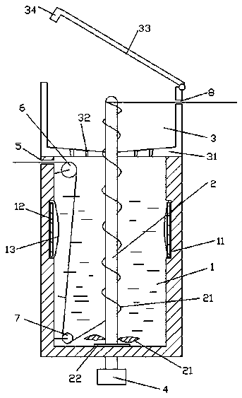
[0015] Such as figure 1 As shown, a spiral dye type yarn printing and dyeing device includes a dye pool 1, a spiral dye column 2 and a centrifugal box 3; the dye pool 1 is a cylindrical dye pool, and the spiral dye column 2 is provided with a threaded channel , the helical dye column 2 is installed in the dye pool 1, and the two ends of the helical dye column 2 extend out of the dye pool 1 respectively, and the bottom end of the helical dye column 2 is connected with a motor 4, and the motor 4 can drive the helical dye column 2 Rotate; above the side wall of the spiral dye post 2 is pro...


PUM

PropertyMeasurementUnit
angleaaaaaaaaaa

Abstract

The invention discloses a spiral dye-type yarn dyeing device which comprises a dye pond, a spiral dye column and a centrifugal box. The dye pond is cylindrical, the spiral dye column is provided with a threaded channel, the spiral dye column is installed in the dye pond, the two ends of the spiral dye column extend out of the dye pond, the bottom end of the spiral dye column is connected with a motor, the motor can drive the spiral dye column to rotate, and the upper side of the side wall of the spiral dye column is provided with a yarn inlet. According to the dying device, spiral dying of yarn can be achieved through the arranged spiral dye column, the yarn can be layered clearly during dying, the phenomenon that the yarn cannot be separated before being wound cannot occur, and a spiral centrifugal function of the spiral dye column is made use of.

Description

technical field [0001] The invention relates to a printing and dyeing device, in particular to a spiral dye type yarn printing and dyeing device. Background technique [0002] The traditional dyeing device mostly uses parallel dyeing rollers for dyeing. The dyeing roller dyeing is more intuitive and the dyeing speed is faster. It can dye many yarns at the same time. It is more suitable for mass production of yarns, but the dyeing roller dyeing usually will The yarn is put into the dye pool. During this process, the yarn is taken out through the dye pool. Since the yarn is stained with a large amount of dye, the dye will drop on the ground or the machine due to gravity, which not only wastes If the dye is contaminated, the machine will be dirty, and the effect of printing and dyeing will not be good. The cost is also high, and the traditional printing and dyeing has poor printing and dyeing effect due to the uneven distribution of dyes and the uncontrollable temperature of d...

Claims


Application Information

Patent Timeline
Patent Type & Authority Patents(China)
IPC IPC(8): D06B3/06D06B15/10
Inventor 徐建龙
Owner JIANGSU SHUANGYING TEXTILE TECH
Features
  • R&D
  • Intellectual Property
  • Life Sciences
  • Materials
  • Tech Scout
  • Unparalleled Data Quality
  • Higher Quality Content
  • 60% Fewer Hallucinations
Learn More