Wave energy generating system

A power generation system and wave energy technology, applied in ocean energy power generation, electromechanical devices, electrical components, etc., can solve the problems of lack of in-depth involvement of power generation devices, low power generation efficiency, complex structure, etc., to avoid equipment vibration problems, weight and the effect of reduced structural strength and simpler design goals

Inactive Publication Date: 2014-12-10
TSINGHUA UNIV
View PDF7 Cites 7 Cited by
  • Summary
  • Abstract
  • Description
  • Claims
  • Application Information

AI Technical Summary

Problems solved by technology

The existing wave power generation devices of the above forms have disadvantages such as weak practicability, complex structure or low power generation efficiency.
In addition, there is no in-depth research on the power generation device of the cluster array at present.

Method used


Image

  • Wave energy generating system
  • Wave energy generating system
  • Wave energy generating system

Examples


Embodiment 1

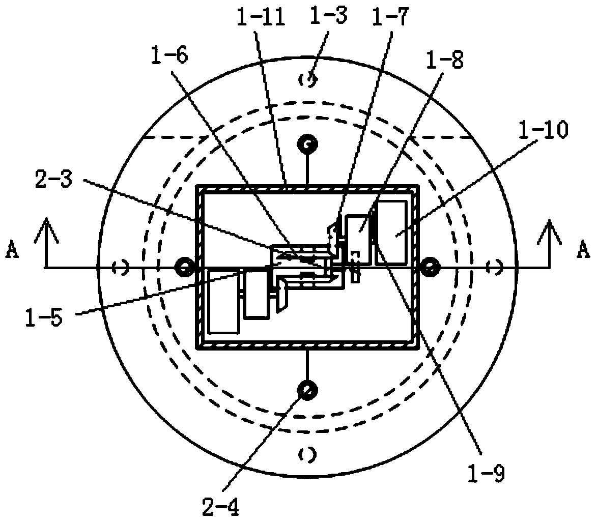
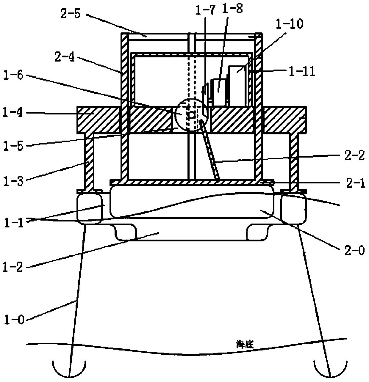
[0022] Such as figure 1 , figure 2 As shown, the wave power generation system provided in this embodiment includes a wave energy conversion device and a wave energy collection device. Wherein, the wave energy conversion device includes a disc type support floating body 1-1 anchored on the seabed through several anchor cables 1-0, and extends downward along the outer edge of the lower end surface of the tail of the support floating body 1-1 to form a section for gathering wave energy. And the arc 1-2 to adjust its direction, the four support rods 1-3 directly above the supporting floating body 1-1 are fastened to a power generation platform 1-4 through fastening connection, and the power generation platform 1-4 A through hole 1-5 is opened in the center of the through hole 1-5, and a mutually symmetrical runner 1-6 is respectively rotated on the front and rear inner walls of the through hole 1-5, and each runner 1-6 is sequentially passed through the power generation platform...

Embodiment 2

[0027] Such as Figure 6 , Figure 7 As shown, the difference between the wave energy generation system provided in this embodiment and the first embodiment is that two wave energy collection floating bodies 2-0 are independently arranged at both ends of the supporting floating body 1-1, and the supporting floating body 1-1 The end face is fastened to an outer frame 1-12, and a surrounding wall 1-13 is arranged at both ends of the outer frame 1-12, and two runners 1 are hinged on the outer frame 1-12 inside each surrounding wall 1-13 -6, one end of the crank 2-2 is hinged on the outer frame 2-1, and the other end passes through the corresponding surrounding wall 1-13 and is fastened to the middle of the shaft 2-3, and the two ends of the shaft 2-3 are rotatably connected to the On the eccentric point of two runners 1-6.

[0028] In the above embodiments, the supporting floating body 1-1 and the wave energy collecting floating body 2-0 are both rectangular structures.

[002...


PUM


Abstract

The invention relates to a wave energy generating system which comprises a wave energy converting device and a wave energy collecting device. The wave energy converting device comprises a supporting floating body, an electricity generating platform, a through hole and rotating wheels, wherein the electricity generating platform is connected over the supporting floating body in a fastened mode, the through hole is formed in the center of the electricity generating platform, the rotating wheels are symmetrically connected to the front wall and the rear wall of the through hole in a rotating mode, each rotating wheel is connected with an electricity generator through a gear, a gearbox and a rotating shaft in sequence, and an enclosure bulkhead is arranged at the position, at the peripheries of the electricity generators, of the electricity generating platform in a surrounding mode. The wave energy collecting device comprises a wave energy collecting floating body, a first outer frame and a crank, and further comprises a plurality of supporting columns, wherein the wave energy collecting floating body is arranged inside the supporting floating body, the first outer frame is connected to the upper end face of the wave energy collecting floating body in a fastened mode, one end of the crank is connected to the position, deviating from the center of the through hole, of the perpendicular corresponding point on the first outer frame in a rotating mode, the other end of the crank is connected to the middle of a horizontal shaft is a fastened mode, the two ends of the horizontal shaft are connected to the eccentric points of the rotating wheels in a rotating mode, the supporting columns are fastened in the peripheral direction of the wave energy collecting floating body, the other end of each supporting column perpendicularly penetrates through the position, at the periphery of the enclosure bulkhead, of the electricity generating platform, and then the other ends of the supporting columns are sequentially connected through a plurality of horizontal connecting rods.

Description

technical field [0001] The invention relates to a power generation system, in particular to a wave energy power generation system. Background technique [0002] Wave power generation technology includes two aspects: collecting wave energy and converting wave energy into electrical energy. In the 1970s, Europe first began to explore how to use ocean wave energy. Up to now, ocean wave energy power generation technology has gradually moved towards the commercial demonstration stage. However, It will take a long time for large-scale promotion and application. The main reasons why wave power generation cannot be popularized and applied on a large scale are: ① harsh marine environment and changing weather conditions; ② existing devices generally have weaknesses in environmental adaptability. Under changing conditions, it can only absorb incoming wave energy of a specific frequency, and the annual power generation hours are limited; ③The power generation efficiency is low. In theo...

Claims


Application Information

Patent Timeline
Patent Type & Authority Applications(China)
IPC IPC(8): F03B13/18H02K7/18
CPCY02E10/30
Inventor 林政张永良
Owner TSINGHUA UNIV
Why Eureka
Try Eureka