Multiple-point-distribution LED lamp

A technology for LED lamps and LED bulbs, applied in the field of LED lighting, to achieve the effects of easy operation and realization, improved heat dissipation efficiency, and good market value

Active Publication Date: 2014-12-10
SHANGHAI TOPLITE TECH
View PDF13 Cites 2 Cited by
  • Summary
  • Abstract
  • Description
  • Claims
  • Application Information

AI Technical Summary

Problems solved by technology

[0002] With the large-scale application of LED, the advantages of being a new light source for emerging lighting are increasingly evident, but at the same time, LED lights require large-area heat dissipation devices

Method used


Image

  • Multiple-point-distribution LED lamp
  • Multiple-point-distribution LED lamp
  • Multiple-point-distribution LED lamp

Examples


Embodiment Construction

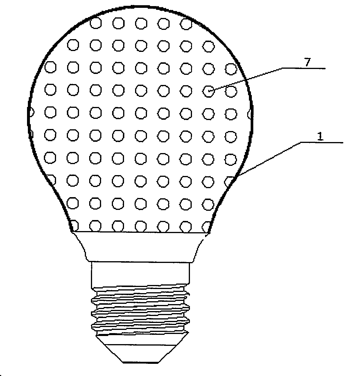
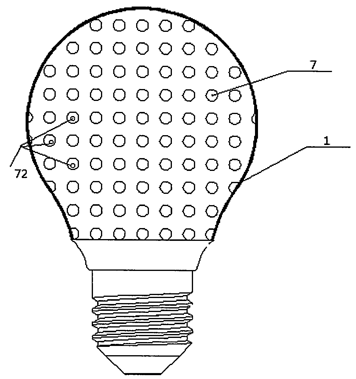
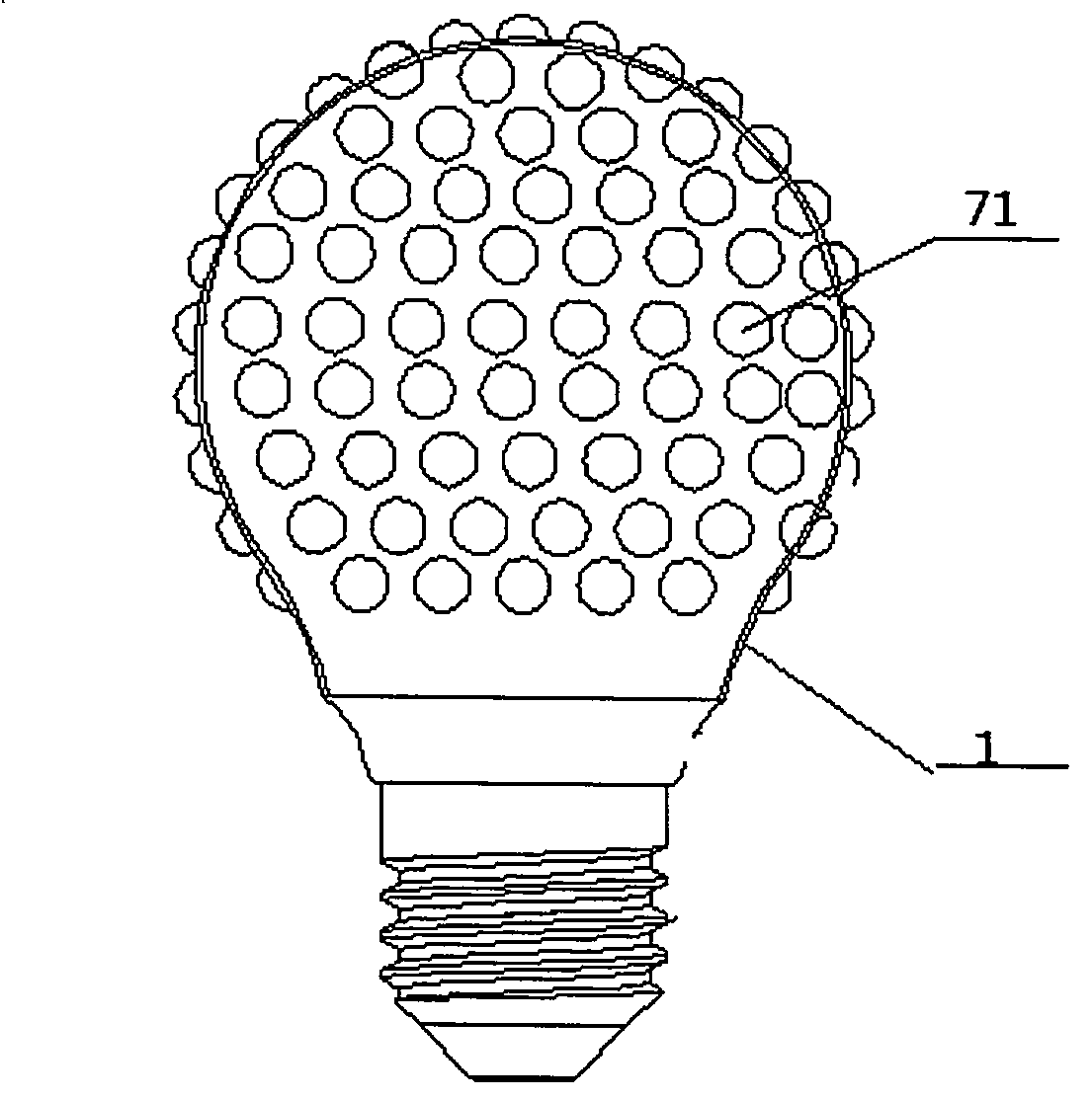
[0034] Those skilled in the art understand that the present invention mainly provides a multi-point distributed LED lamp. The advantage of using a multi-point distributed LED lamp is that it can make the LED lamp have better heat dissipation performance, and its function of improving heat dissipation efficiency is mainly The heat dissipation point 7 is provided on the LED bulb shell 1 to achieve this. The heat dissipation point 7 can additionally increase the heat dissipation area, so that the heat in the bulb shell 1 can be dissipated more quickly and fully.

[0035] specifically, figure 1 A schematic structural diagram of an LED lamp according to a specific embodiment of the present invention is shown. The present invention provides a multi-point distributed LED lamp, which at least includes an LED bulb shell 1, an LED light-emitting chip group 3 ( figure 1 not shown), the LED light-emitting chipset 3 is placed in the LED light bulb shell 1, wherein, the outer surface of th...


PUM


Abstract

The invention provides a multiple-point-distribution LED lamp. The multiple-point-distribution LED lamp is characterized by at least comprising an LED lamp bulb shell (1) and an LED light-emitting chip set (3); the LED light-emitting chip set (3) is arranged in the LED lamp bulb shell (1); a plurality of radiating points (7) are arranged on the outer surface of the LED lamp bulb shell (1). The radiating points (7) are arranged on the outer surface of the LED lamp bulb shell (1), the radiating surface of the LED lamp bulb shell (1) is heightened so that heat generated when the LED lamp emits light can be rapidly diffused to air, and radiating of the LED lamp is more sufficient accordingly. The radiating mode is easy and convenient to use and easy to operate and implement, and the good market value is achieved.

Description

technical field [0001] The invention relates to the field of LED lighting, in particular to an LED lamp, in particular to a multi-point distributed LED lamp. Background technique [0002] With the large-scale application of LED, the advantages of being a new light source for emerging lighting are increasingly evident, but at the same time, LED lights require a large-area heat dissipation device. The bulb lamps that people are accustomed to using in daily life have a common feature: the glass body has an ellipsoidal shell, and the spherical surface of the bulb emits light. Those skilled in the art know that heat dissipation requires sufficient heat dissipation area and air for convection, the distance from the heat source to the heat dissipation surface is as short as possible, and the thermal resistance between the heat source and the heat dissipation surface is low is an ideal heat dissipation structure. But at present, most LED light bulbs shrink the glass shell, and add ...

Claims


Application Information

Patent Timeline
Patent Type & Authority Applications(China)
IPC IPC(8): F21S2/00F21V29/00F21V23/00F21Y101/02
Inventor 李建胜
Owner SHANGHAI TOPLITE TECH
Why Eureka
Try Eureka