
Air filter device and purpose thereof

An air filter device and filter device technology, which is applied in the field of air filter devices or components, can solve the problems of difficult opening of the panel, danger, and influence on indoor air quality, etc., and achieve the effect of novel design, excellent performance, and firm hand feeling

Active Publication Date: 2014-12-10
ZHEJIANG GOLDENSEA ENVIRONMENT TECH
View PDF6 Cites 4 Cited by
  • Summary
  • Abstract
  • Description
  • Claims
  • Application Information

AI Technical Summary

Problems solved by technology

[0007] ①It is easy to accumulate dust, which affects the cooling and heating effect;
[0008] ②The accumulated dust on the filter screen will enter the room with the air flow, affecting the indoor air quality; and
[0009] ③ It is necessary to regularly open the air intake grille and remove the filter for cleaning. It is often difficult to open the panel, and it is necessary to use tools such as tables and chairs to operate. The operation is cumbersome and dangerous
[0011] ①When cleaning, some filters need to stick out of the machine, affecting the beauty of home decoration;
[0012] ②The filter screen is rolled up inside the machine, adopting free extension or meandering, which increases the volume and cost of the indoor unit; and
[0013] ③The filter screen is not cleaned cleanly and needs to be cleaned manually again
[0014] Due to the above-mentioned technical problems still exist in the prior art, there is an urgent need for a new filter device, especially a filter device or component used in a household air conditioner, thereby providing a filter that not only solves the impact of dust accumulation on the air filter screen Cooling and heating effect problems, troubles caused by manual cleaning of the filter, automatic dust removal affecting the appearance of home decoration, and problems such as unclean filter cleaning; moreover, the dusty filter can be automatically collected multiple times according to user settings. Products that release clean filters

Method used


Image

  • Air filter device and purpose thereof
  • Air filter device and purpose thereof
  • Air filter device and purpose thereof

Examples


Embodiment Construction

[0064] The filtering device of the present invention will be described in detail below with reference to the accompanying drawings. It should be noted that the following embodiments are only for the purpose of illustration, and are by no means intended to limit the protection scope of the present invention.

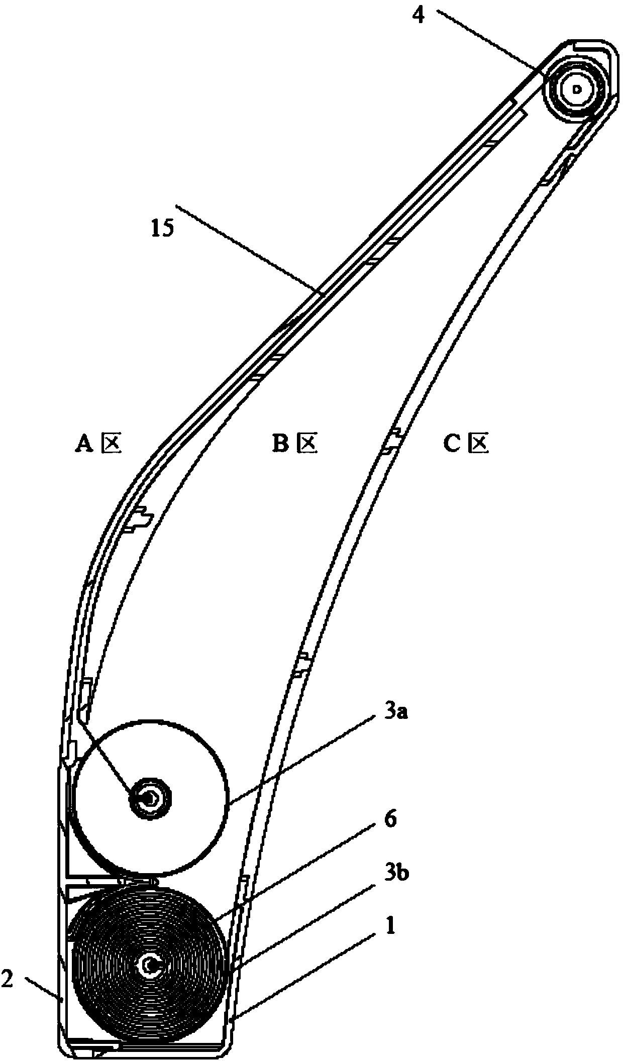
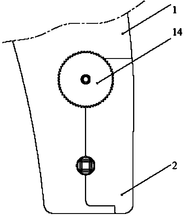
[0065] The structure of the filter device of the present invention is as figure 1 with 2 shown. The filtering device comprises: a casing (1), a cover plate (2), a retractable net mechanism (3) (upper end 3a and lower end 3b), a transfer mechanism (4), a gear (14) and a filter net assembly (6).

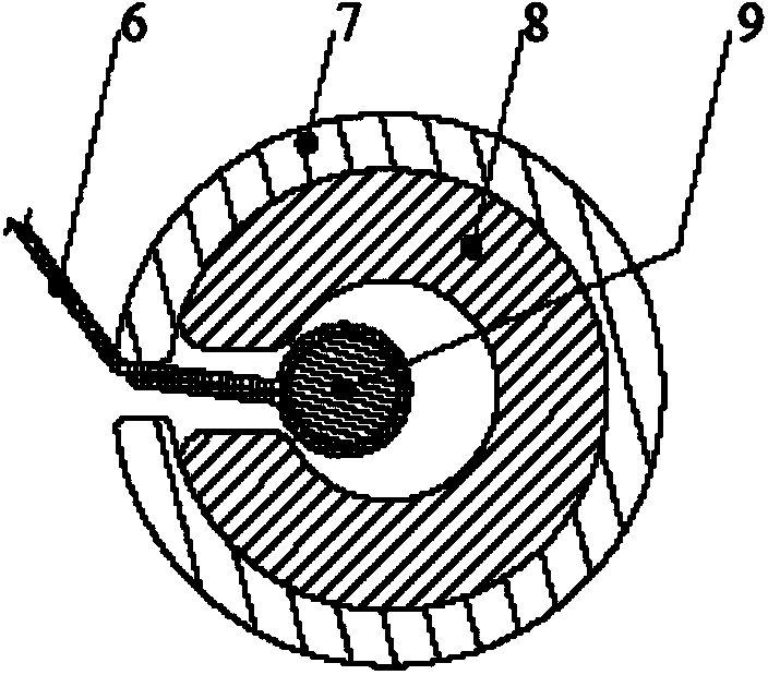
[0066] Specifically, guide grooves (15) are provided on the left and right sides of the housing (1), and limiting pieces (5) are provided inside. The retractable net mechanism (3) is composed of a rotating shaft (7), two end caps (8) and a steel wire (9), and a gear (14) is used to connect the retractable net mechanism (3) together and Make sure to sync. The transfer mechanis...


PUM


Abstract

The invention relates to an air filter device which comprises an outer shell 1, a cover plate 2, net winding and unwinding mechanisms 3a and 3b, a transfer mechanism 4, a gear 14 and a filter net component 6. The net winding and unwinding mechanism 3a or 3b is connected with the gear 14, and the filter net component 6 is led out from the net winding and unwinding mechanism 3a or 3b, covers an air inlet face, then covers an air outlet face after passing through the transfer mechanism 4, and then returns to the net winding and unwinding mechanism 3b or 3a. The filter net component 6 is synchronous with the net winding and unwinding mechanisms 3a and 3b through the gear 14, the filter net component 6 circulates in the net winding and unwinding mechanism 3a or 3b through the transfer mechanism 4 to be collected by the net winding and unwinding mechanism 3a or 3b, and the other net winding and unwinding mechanism 3b or 3a synchronously releases the filter net component 6. The air filter device can be applied to filter devices or components in air conditioners, and is used for filtering out and adsorbing PM particles in air.

Description

technical field [0001] The present invention relates to an air filter device and its application, in particular to an air filter device or components used in household air conditioners. Background technique [0002] At present, the air conditioner generally adopts two-side or three-side air intake, and the air filter is placed on the air intake grille. When the air conditioner is working, the air enters through the air intake grille, is purified by the air filter, passes through the heat exchanger, and then comes out from the air outlet, so that the indoor air is conditioned by circulation. [0003] At present, some air-conditioning filters adopt a structure that is fully removable and easy to clean or automatically cleaned, among which: [0004] (1) The fully dismantled, washable and easy-to-clean structure is as follows: the filter screen is a separate component, which can be taken out or inserted from the air inlet grille of the air conditioner by opening the panel of th...

Claims


Application Information

Patent Timeline
Patent Type & Authority Applications(China)
IPC IPC(8): F24F13/28
Inventor 丁宏广唐海军
Owner ZHEJIANG GOLDENSEA ENVIRONMENT TECH
Learn More