
A continuous catchment system

A technology of water catcher and water unit, which is applied in the direction of evaporator/condenser, refrigeration safety arrangement, refrigeration components, etc., and can solve the problems affecting the normal use of continuous pumping type high-humidity decompression storage device and the water catcher cannot work continuously and other issues, to achieve the effects of reducing energy consumption, automatic and rapid drainage, and reducing load

Inactive Publication Date: 2017-01-25
TIANJIN UNIV OF COMMERCE
View PDF7 Cites 0 Cited by
  • Summary
  • Abstract
  • Description
  • Claims
  • Application Information

AI Technical Summary

Problems solved by technology

Due to the existence of the defrosting process, the water trap cannot work continuously
However, the pumping system of the continuous pumping type high-humidity decompression storage device needs to work continuously, which requires the supporting water catcher to work continuously. The water catcher affected the normal use of the continuous pumping high-humidity decompression storage device

Method used


Image

  • A continuous catchment system

Examples


Embodiment Construction

[0014] The present invention will be described in further detail below in conjunction with the accompanying drawings and specific embodiments.

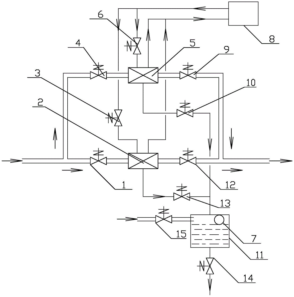
[0015] The schematic diagram of the continuous water catch system of the present invention is as figure 1 As shown, it includes a refrigeration unit 8 and a water-catching device, and the water-catching device is formed by connecting a first water-catching unit and a second water-catching unit in parallel. The first water catch unit is composed of the first air intake electric control valve 4, the first water catcher 5 and the first air outlet electric control valve 9 connected in series, and the second water catch unit is composed of the second air intake electric control valve 1 , The second water catcher 2 and the second gas outlet electric control valve 12 are connected in series. A first electric heating tube for thermoelectric defrosting is installed in the first water trap 5 , and a second electric heating tube for thermoelect...


PUM


Abstract

The invention discloses a continuous water catching system, and provides a system which can realize water catching work continuously without being affected by defrosting. The continuous water catching system comprises a refrigerating unit and a water catching device. The water catching device is formed by connecting a first water catching unit and a second water catching unit in parallel. The first water catching unit is formed by connecting a first air inlet electric control valve, a first water catcher and a first water outlet electric control valve in series. The second water catching unit is formed by connecting a second air inlet electric control valve, a second water catcher and a second air outlet electric control valve in series. A first electric heating pipe used for conducting thermoelectric defrosting is arranged in the first water catcher, and a second electric heating pipe used for conducting thermoelectric defrosting is arranged in the second water catcher. A time controller controls the first water catcher and the second water catcher to conduct water catching and defrosting alternately by controlling connection and disconnection of the first air inlet electric control valve, the first air outlet electric control valve, the second air inlet electric control valve, the second air outlet electric control valve, the first electric heating pipe, the second electric heating valve, a first water draining control valve, a second water draining control valve, a first liquid supply valve and a second liquid supply valve.

Description

technical field [0001] The invention relates to a continuous water capture system capable of continuously capturing water vapor. Background technique [0002] The water trap has different names in different industries. In the chemical industry, it is called a gas-solid phase change heat exchanger. In the refrigeration industry, it is called an evaporator. In the vacuum industry, it is called a water vapor condenser or a water vapor transfer. condensate pump. No matter what its name is, its function is to capture water vapor, and extract the water vapor from the gaseous state to directly condense into frost. [0003] For the pumping system of the high-humidity decompression storage device, a water trap is installed before the vacuum pump, which can capture most of the water vapor in the high-humidity air extracted from the decompression storage room, and the air treated by the water trap enters the vacuum pump , greatly reducing the load of the vacuum pump, thereby reducing...

Claims


Application Information

Patent Timeline
Patent Type & Authority Patents(China)
IPC IPC(8): F25B39/02F25B49/00
Inventor 申江丁峰
Owner TIANJIN UNIV OF COMMERCE
Learn More