An environmentally friendly particle circulation system suitable for drilling

A circulatory system and particle technology, used in drilling equipment, earth-moving drilling, flushing wells, etc., can solve the problems of many mud leakage points, complicated installation, inconvenient installation and transportation, etc.

Active Publication Date: 2018-06-22
BC P INC CHINA NAT PETROLEUM CORP +2
View PDF7 Cites 0 Cited by
  • Summary
  • Abstract
  • Description
  • Claims
  • Application Information

AI Technical Summary

Problems solved by technology

The problems existing in the particle circulation path of the particle impact drilling system in the prior art are: there are many mud leakage points, which is easy to cause environmental pollution; cuttings need to be manually processed, which is labor-intensive; there are many equipments, scattered installation locations, complex installation, and long time-consuming
[0010] The negative pressure jet particle impact drilling injection device disclosed in this patent document uses a self-rotating jet anti-blocking nozzle to achieve omnidirectional and multi-angle agitation at the outlet of the high-pressure particle injection tank, which can solve the problem of blockage at the bottom of the high-pressure particle injection tank. However, this device also cannot achieve continuous injection of particles, and the drilling speed is limited; moreover, the mass and volume of the high-pressure particle injection tank used are relatively large, making installation and transportation inconvenient

Method used


Image

  • An environmentally friendly particle circulation system suitable for drilling
  • An environmentally friendly particle circulation system suitable for drilling
  • An environmentally friendly particle circulation system suitable for drilling

Examples


Embodiment 1

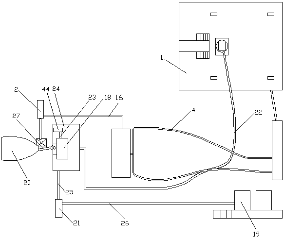
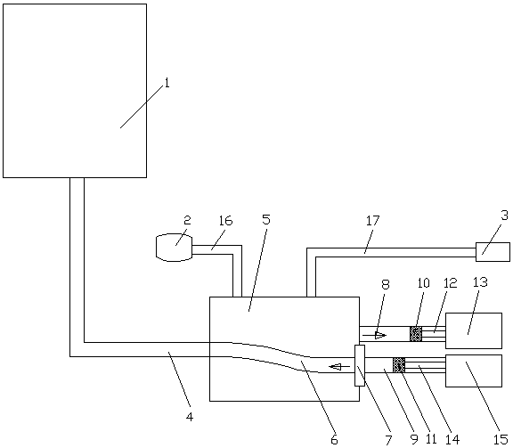
[0048] see figure 1 and figure 2 , an environmentally friendly particle circulation system suitable for drilling, including a drilling floor 1, an injection device and a recovery device, the injection device includes a slurry pump 2, a screw conveyor 3 and a particle mixing unit connected to the drilling riser through a high-pressure pipeline 4 Hopper 5, the particle mixing hopper 5 is provided with a reversing pipe 6, the reversing pipe 6 is connected with a swing hydraulic cylinder 7 that drives the reversing pipe 6 to swing left and right, the particle mixing hopper 5 is connected with a first delivery cylinder 8 and The second conveying cylinder 9, the first conveying cylinder 8 is provided with a first piston 10, the second conveying cylinder 9 is provided with a second piston 11, and the first piston 10 is connected to the first hydraulic cylinder 13 through the first piston rod 12 , the second piston 11 is connected to the second hydraulic cylinder 15 through the seco...

Embodiment 2

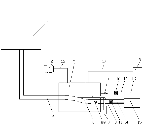
[0051] see figure 1 , image 3 and Figure 4 , an environmentally friendly particle circulation system suitable for drilling, including a drilling floor 1, an injection device and a recovery device, the injection device includes a slurry pump 2, a screw conveyor 3 and a particle mixing unit connected to the drilling riser through a high-pressure pipeline 4 Hopper 5, the particle mixing hopper 5 is provided with a reversing pipe 6, the reversing pipe 6 is connected with a swing hydraulic cylinder 7 that drives the reversing pipe 6 to swing left and right, the particle mixing hopper 5 is connected with a first delivery cylinder 8 and The second conveying cylinder 9, the first conveying cylinder 8 is provided with a first piston 10, the second conveying cylinder 9 is provided with a second piston 11, and the first piston 10 is connected to the first hydraulic cylinder 13 through the first piston rod 12 , the second piston 11 is connected to the second hydraulic cylinder 15 thro...

Embodiment 3

[0055] see figure 1 , Figure 4 and Figure 8 , an environmentally friendly particle circulation system suitable for drilling, including a drilling floor 1, an injection device and a recovery device, the injection device includes a slurry pump 2, a screw conveyor 3 and a particle mixing unit connected to the drilling riser through a high-pressure pipeline 4 Hopper 5, the particle mixing hopper 5 is provided with a reversing pipe 6, the reversing pipe 6 is connected with a swing hydraulic cylinder 7 that drives the reversing pipe 6 to swing left and right, the particle mixing hopper 5 is connected with a first delivery cylinder 8 and The second conveying cylinder 9, the first conveying cylinder 8 is provided with a first piston 10, the second conveying cylinder 9 is provided with a second piston 11, and the first piston 10 is connected to the first hydraulic cylinder 13 through the first piston rod 12 , the second piston 11 is connected to the second hydraulic cylinder 15 thr...


PUM


Abstract

The invention discloses an environment-protection circulating system suitable for well drilling and belongs to the technical field of oil gas drilling engineering. The Environment-protection circulating system comprises a slurry pump, a screw rod conveyer and a particle hybrid bucket, wherein a reversing pipe is disposed in the particle hybrid bucket; the reversing pipe is connected with a swinging hydraulic cylinder; the particle hybrid bucket is connected with a first conveying cylinder and a second conveying cylinder; one end of the reversing pipe is communicated with a high pressure pipeline and the other end is communicated with the first conveying cylinder or the second conveying cylinder; the slurry pump and the screw rod conveyer are respectively communicated with the particle hybrid bucket; a recovery device comprises a magnetic separator, a drilling screw vibrating screen, a rotary storage tank and a mortar pump; a mud slurry tank is connected under the magnetic separator; the mud slurry tank is connected with the mortar pump; the mortar pump is connected with the drilling screw vibrating screen; the magnetic separator is connected with a horizontal conveyer; the horizontal conveyer is connected with the rotary storage tank; and the rotary storage tank is connected with a slurry pump. By the use of the environment-protection circulating system suitable for well drilling, continuous particle injection can be guaranteed; practical drilling well impact efficiency is enhanced; and mud leakage points can be reduced and environment pollution can be reduced.

Description

technical field [0001] The invention relates to the technical field of oil and gas drilling engineering, in particular to an environment-friendly particle circulation system suitable for drilling. Background technique [0002] The current conventional drilling technology is to use the drill pressure and rotation of the bottom hole drill bit to mechanically break the rock and achieve the purpose of drilling. The drilling floor is equipped with a rotary control head. When encountering deep hard formations and strong abrasive formations, Only relying on the mechanical action of the drill bit to break rock, the function of mud is only to carry cuttings, and the joint rock breaking effect of hydraulic and mechanical cannot be realized, and there are problems of slow drilling speed, long cycle time and high cost. [0003] In recent years, particle impact drilling technology has been widely used as a revolutionary speed-increasing technology; particle impact drilling is a method of...

Claims


Application Information

Patent Timeline
Patent Type & Authority Patents(China)
IPC IPC(8): E21B7/16E21B21/00
Inventor 李伟成姚建林陈晓彬陈立黄伟周刚胡畔付晓平
Owner BC P INC CHINA NAT PETROLEUM CORP
Why Eureka
Try Eureka