Spatial position simulation and calibration method

A technology of spatial position and calibration method, applied in the direction of measuring devices, optical devices, instruments, etc., to achieve the effect of high centering accuracy, low cost, and strong universality

Inactive Publication Date: 2014-12-10
BEIHANG UNIV
View PDF5 Cites 9 Cited by
  • Summary
  • Abstract
  • Description
  • Claims
  • Application Information

AI Technical Summary

Problems solved by technology

However, there is no universal high-precision spatial calibration method for multiple objects without direct contact.

Method used


Image

  • Spatial position simulation and calibration method
  • Spatial position simulation and calibration method
  • Spatial position simulation and calibration method

Examples


Embodiment Construction

[0042] The present invention will be described in further detail below with reference to the accompanying drawings.

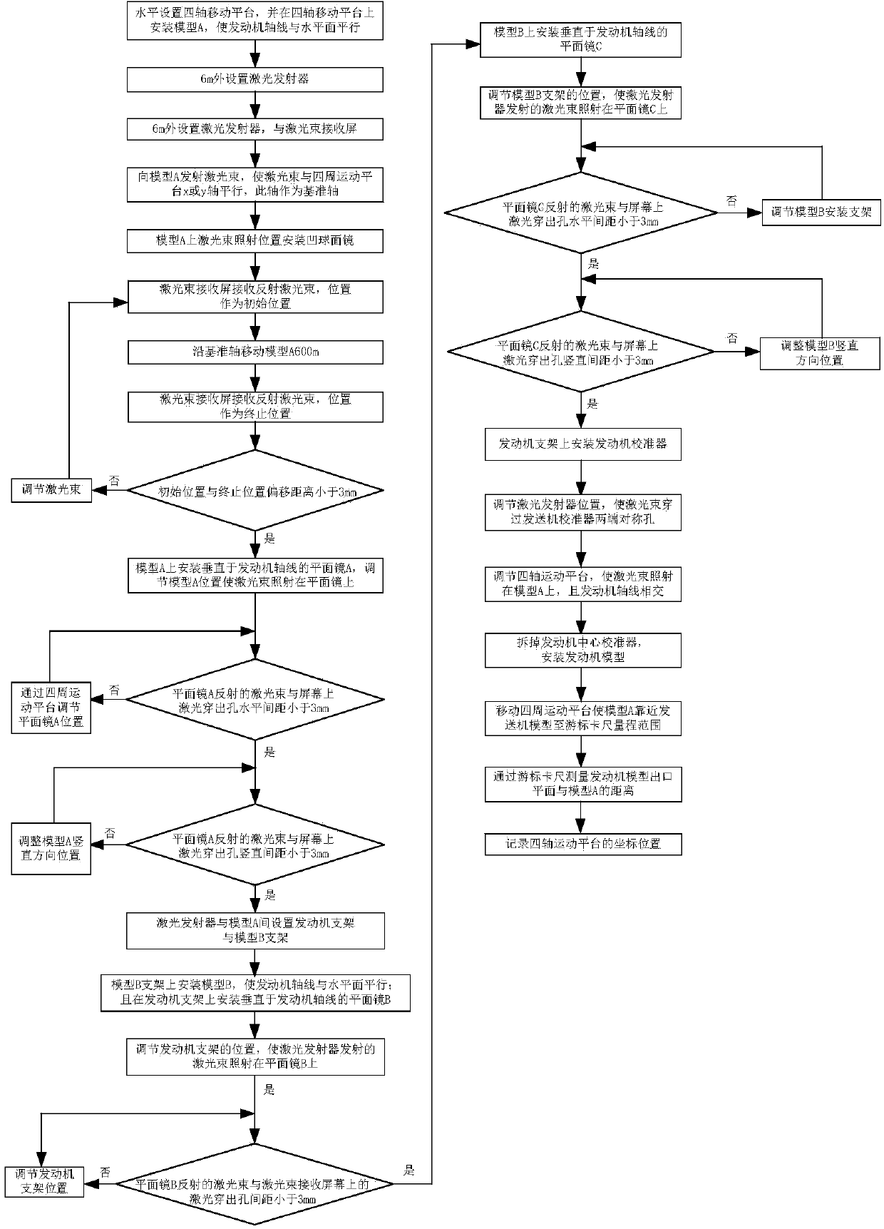
[0043] The spatial position simulation and calibration method of the present invention is specifically completed through the following steps, such as: figure 1 shown:

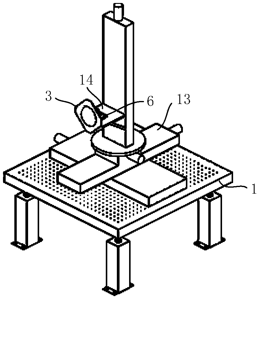
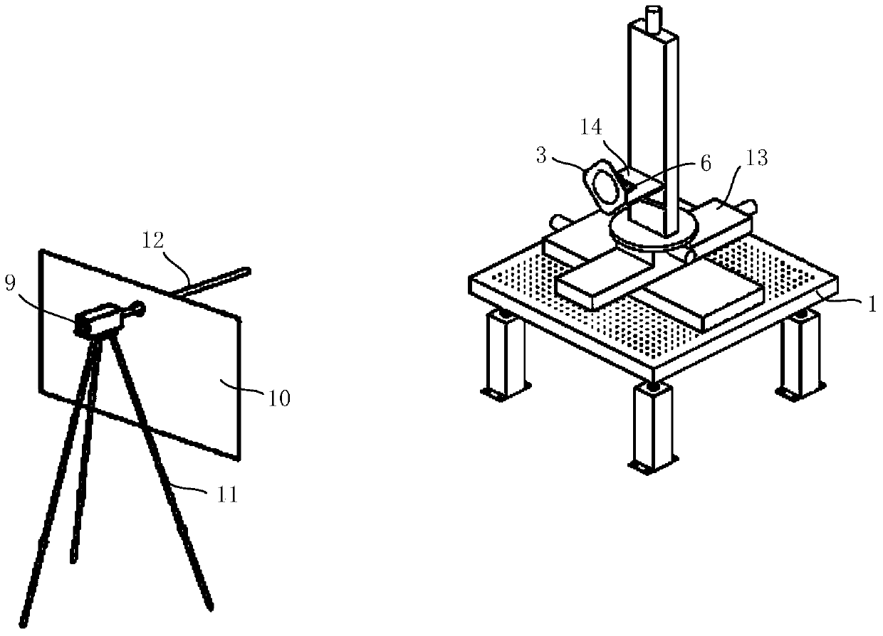
[0044] Step A: Place the assembled four-axis motion platform 13 on the optical platform A1, such as figure 2As shown, the plane formed by the x and y axes of the four-axis motion platform 13 is made parallel to the surface of the optical platform A1; the optical platform A1 is leveled with a high-precision level. Let the separated or docked parts in the spacecraft (such as the lander and ascender of the Chang'e series lunar lander.) be part A and part B respectively; according to the actual spacecraft size, the spacecraft is scaled or reduced in equal proportions, and the The part A, part B and the spacecraft engine are made into models, which are model A3, model B4 and engine model 5 respect...


PUM


Abstract

The invention discloses a spatial position simulation and calibration method. The method includes: utilizing a laser beam reflected by a plane mirror to perform space angle calibration between models A and B and an engine, in other words, replacing an axis of the engine with the laser beam, mounting the plane mirror on a plane perpendicular to the axis, if the laser is not perpendicular to the plane, forming an included angle between an incident laser beam and the reflected laser beam, and determining size of angular deviation by comparing positions of the incident laser beam and the reflected laser beam at a remote location; utilizing an engine center calibrator to align the model B and the engine, in other words, enabling the laser beam to pass through a center hole of the engine enter calibrator, adjusting a three-dimensional mobile device to enable the laser beam passing through the center hole to irradiate the center of the model A, and completing spatial position simulation and calibration between the models A and B. the method has the advantages that relative position adjustment of the engine and test piece models which are contactless is realized in three-dimensional space conveniently, accuracy of adjustment is high, and the angular deviation and positional deviation between the modes are not more than 0.1 degree and 0.2mm respectively.

Description

technical field [0001] The invention relates to a space position simulation and calibration method, which is suitable for ground simulation tests such as lunar take-off of lunar exploration spacecraft, separation of stars and arrows, etc., and can also be used for other space position calibration. Background technique [0002] The lunar take-off of the lunar probe and the separation of the star and the rocket are all important links in the space mission process. In order to ensure the successful completion of the space mission, it is necessary to conduct ground tests to verify these processes, and one of the keys to these ground simulation tests is the relative position in space. For example, when the lunar exploration spacecraft takes off from the lunar surface, the ascender is separated from the landing platform, and the ascender leaves the lunar surface and returns to the earth relying on the thrust of the engine. When the ground simulation test is carried out for this pro...

Claims


Application Information

Patent Timeline
Patent Type & Authority Applications(China)
IPC IPC(8): G01B11/00
Inventor 贺碧蛟张明星蔡国飙
Owner BEIHANG UNIV
Why Eureka
Try Eureka