
In-place measuring method for runout of high precision gyrorotor

A measurement method and a technology of a rotating body, which are applied in the direction of measuring devices, instruments, etc., can solve problems such as the inability to separate the rotation error of the machine tool spindle and the limited accuracy of runout information.

Active Publication Date: 2014-12-10
浙江金点玩具有限公司
View PDF7 Cites 28 Cited by
  • Summary
  • Abstract
  • Description
  • Claims
  • Application Information

AI Technical Summary

Problems solved by technology

[0005] In order to overcome the shortcomings of the prior art that the rotation error of the machine tool spindle cannot be separated and the accuracy of the runout information obtained is limited, the present invention provides a high-precision rotary body runout in-situ measurement that can separate the rotation error of the machine tool spindle and provide high-precision runout information method

Method used


Image

  • In-place measuring method for runout of high precision gyrorotor
  • In-place measuring method for runout of high precision gyrorotor

Examples


Embodiment Construction

[0054] With reference to accompanying drawing, further illustrate the present invention:

[0055] An in-situ measurement method for the runout of a high-precision rotary body, comprising the following steps:

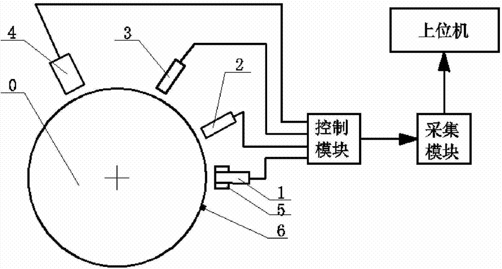
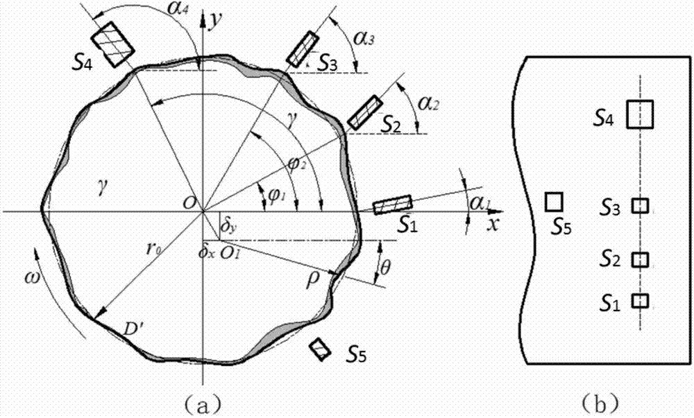
[0056] 1) Stop the measured shaft and install laser displacement sensors, eddy current sensors and Hall sensors respectively, such as figure 1 As shown, the laser displacement sensor, eddy current sensor and Hall sensor are respectively aligned with the measured axis, the laser displacement sensor and the eddy current sensor are located on the same circle, which is coaxial with the measured rotating body, and the eddy current sensor has 3 One, the Hall sensor is set on one of the eddy current sensors; the laser displacement sensor, the eddy current sensor and the Hall sensor are respectively connected to the processor; a mark that can be recognized by the Hall sensor is installed on the measured shaft;

[0057] 2), such as figure 2 As shown, the position of each senso...


PUM


Abstract

The invention discloses an in-place measuring method for runout of a high precision gyrorotor. The in-place measuring method comprises the following steps of: stopping rotation of a shaft to be measured, installing a laser displacement sensor, electrical vortex sensors and Hall sensors, and installing a sign that can be identified by the Hall sensors on the shaft to be measured; adjusting positions of the sensors by taking the first electrical vortex sensor sleeved with the Hall sensor as a standard; enabling the surface of the shaft to be measured to be adsorbed with four pieces of magnetic steel which serve as signs can be identified by the Hall sensors; rotating the shaft to be measured, after the rotating speed is stable, collecting periodical pulse signals output by the Hall sensors; adjusting the shaft to be measured to have the proper rotating speed; obtaining signals measured by each electrical vortex sensor; working out an comprehensive runout error, and working out a runout value of a workpiece to be measured on a measuring section. The in-place measuring method for the runout of the high precision gyrorotor has the advantages of being capable of separating rotating error of a machine tool spindle, and providing runout of the high precision gyrorotor with high precision runout information.

Description

technical field [0001] The invention relates to an in-situ measurement method of a revolving body. technical background [0002] Eddy current sensors are currently widely used in industrial automation systems, which have the advantages of non-contact measurement, high linearity, high resolution, and low requirements for the measurement environment. In industrial automation systems, eddy current sensors are often used to detect the vibration information of rotary equipment, so as to achieve the purpose of real-time monitoring of equipment status. Electrical runout characterizes the inhomogeneity of the electromagnetic properties of the surface material of the revolving body parts, and mechanical runout characterizes the circumferential geometric shape error of the revolving body. The sum of electrical runout and mechanical runout is called total runout. The integrated beating signal will be mixed into the signal monitored by the eddy current sensor, which will affect the acc...

Claims


Application Information

Patent Timeline
Patent Type & Authority Applications(China)
IPC IPC(8): G01B21/00
Inventor 叶晓平游张平杨将新刘鸣洲
Owner 浙江金点玩具有限公司
Learn More