Method and equipment for determining apparent dip angles of target layers of drill wells

A technology of target horizon and apparent inclination, applied in the field of geophysical exploration, can solve problems such as inability to guarantee well inclination and consistency

Active Publication Date: 2014-12-10
BC P INC CHINA NAT PETROLEUM CORP +1
View PDF5 Cites 15 Cited by
  • Summary
  • Abstract
  • Description
  • Claims
  • Application Information

AI Technical Summary

Problems solved by technology

[0006] The purpose of the exemplary embodiment of the present invention is to solve the technical problem that it is impossible to ensure that the inclination angle and the apparent dip angle of the drilling target lay

Method used


Image

  • Method and equipment for determining apparent dip angles of target layers of drill wells
  • Method and equipment for determining apparent dip angles of target layers of drill wells
  • Method and equipment for determining apparent dip angles of target layers of drill wells

Examples


Embodiment Construction

[0031] The following description with reference to the accompanying drawings is provided to assist in a comprehensive understanding of embodiments of the present invention as defined by the claims and their equivalents. Various specific details are included to aid in understanding but are to be regarded as exemplary only. Accordingly, those of ordinary skill in the art will recognize that various changes and modifications of the embodiments described herein can be made without departing from the scope and spirit of the invention. Also, descriptions of well-known functions and constructions are omitted for clarity and conciseness.

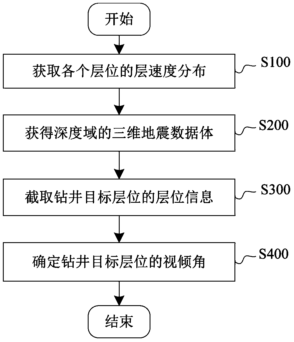
[0032] figure 1 A flowchart showing a method for determining the apparent dip of a drilling target horizon according to an exemplary embodiment of the present invention. Here, as an example, the method may be realized by a device for determining the apparent dip of the drilling target formation, or may be completely realized by a computer program....


PUM


Abstract

The invention provides a method and equipment for determining apparent dip angles of target layers of drill wells. The method includes acquiring layer velocity distribution of various layers according to drill well data and seismic data of the various drill wells; performing time-depth conversion on time-domain three-dimensional seismic data volumes by the aid of the acquired layer velocity distribution of the various layers to acquire depth-domain three-dimensional seismic data; capturing layer information of the target layers of the drill wells from the depth-domain three-dimensional data volumes; determining the apparent dip angles of the target layers of the drill wells on the basis of the layer information of the target layers of the drill wells. Each layer comprises a plurality of surface elements, and respective layer velocities of the various surface elements of the corresponding layers are indicated by the layer velocity distribution. The layer information of the target layers of the drill wells comprises horizontal coordinates and depth coordinates of common center points of the surface elements on the target layers of the drill wells. The method and the equipment have the advantage that the directional wells can be guided in thin reservoirs in regions with high, deep and complicated structures.

Description

technical field [0001] The present invention generally relates to the field of geophysical exploration, and more specifically relates to a method and equipment for determining the apparent dip angle of a drilling target layer in a high and steep structure area. Background technique [0002] In recent years, in the development process of most oil and gas fields in high and steep structural areas such as eastern Sichuan, in order to meet the development needs of thin reservoirs, more and more highly deviated wells and horizontal wells are used in the design process of directional wells technology. However, the thickness of many thin reservoirs in the high-steep structural area in eastern Sichuan is only about 10m, and after drilling into the target area, the well inclination angle is as high as 70 degrees or even 90 degrees sometimes, which causes drilling problems in engineering implementation. The difficulty is increasing. In order to increase the footage of the drilling tr...

Claims


Application Information

Patent Timeline
IPC IPC(8): G01V1/40
Inventor 王征覃发兰王兰英朱鹏宇
Owner BC P INC CHINA NAT PETROLEUM CORP
Why Eureka
Try Eureka