
Method and system for diagnosing hardware module faults based on indicator lights

A hardware module and hardware failure technology, which is applied to the detection of faulty computer hardware, hardware monitoring, etc., can solve the problems of troublesome detection methods and low efficiency, and achieve the effect of saving after-sales service, saving time, and improving maintenance efficiency

Inactive Publication Date: 2014-12-10
GUANGDONG OPPO MOBILE TELECOMM CORP LTD
View PDF8 Cites 22 Cited by
  • Summary
  • Abstract
  • Description
  • Claims
  • Application Information

AI Technical Summary

Problems solved by technology

[0003] However, if there are many circuit modules or hardware modules, it is difficult to directly obtain which module has a problem, and technicians need to eliminate or confirm one by one. The detection method is cumbersome and inefficient.

Method used


Image

  • Method and system for diagnosing hardware module faults based on indicator lights
  • Method and system for diagnosing hardware module faults based on indicator lights
  • Method and system for diagnosing hardware module faults based on indicator lights

Examples


Embodiment 1

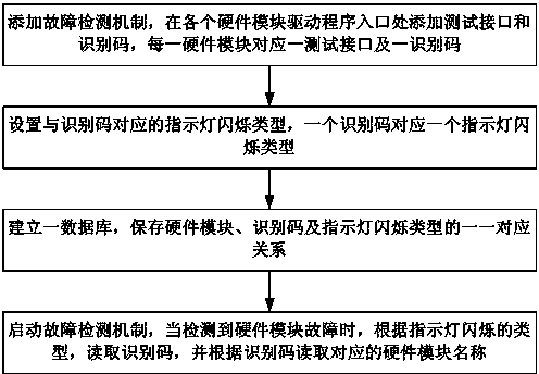
[0037] The method flowchart of embodiment 1 is as figure 1 As shown, a method for diagnosing hardware module faults based on indicator lights is applied to mobile terminal products, such as mobile phones, handheld computers and other electronic products, and setting indicator lights on mobile terminals includes the following steps:

[0038] Step S101. Add a fault detection mechanism, add a test interface and an identification code at the entrance of each hardware module driver, and each hardware module corresponds to a test interface and an identification code; Added failure detection mechanism. For example, the fault detection mechanism can be set in the form of an application program or software. After the fault detection mechanism is added to the mobile terminal, the hardware module of the mobile terminal product can be automatically detected in real time after the fault detection mechanism is started. In order to cooperate with the fault detection mechanism, a test interf...

Embodiment 2

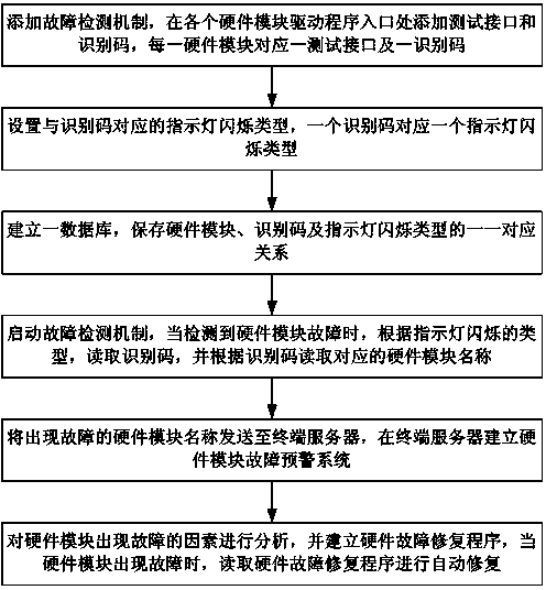
[0053] Embodiment 2 is different from Embodiment 1 in that an automatic early warning system and an automatic repair function are set, so that the mobile terminal hardware module can easily and quickly perform self-repair when a fault occurs, and when a high-frequency fault occurs in a certain module, it can Feedback timely and effective information to the manufacturer for maintenance and improvement.

[0054] The method flowchart of embodiment 2 is as image 3 As shown, a method for diagnosing hardware module faults based on indicator lights includes the following steps:

[0055] Step S201. Add a fault detection mechanism, add a test interface and an identification code at the entrance of each hardware module driver, and each hardware module corresponds to a test interface and an identification code; in order to better diagnose the hardware module, in the mobile terminal Added failure detection mechanism. For example, the fault detection mechanism can be set in the form of ...


PUM


Abstract

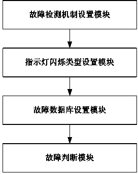
The invention discloses a method and system for diagnosing hardware module faults based on indicator lights. The method includes the steps that first, a fault detection mechanism is added, a test interface and an identification code are added at each hardware module drive program inlet, and each hardware module corresponds to one test interface and one identification code; second, the indicator light flickering types corresponding to the identification codes are set, and one identification code corresponds to one indicator light flickering type; third, a database is established, and the one-to-one corresponding relation of the hardware modules, the identification codes and the indicator light flickering types is stored; fourth, the fault detection mechanism is started, when the hardware module faults are detected, the identification codes are read according to the indicator light flickering types, and corresponding hardware module names are read according to the identification codes. According to the method and system for diagnosing the hardware module faults based on the indicator lights, when the faults happen, the hardware faults can be detected quickly, time is saved, overhauling efficiency is improved, and analysis early warning and automatic repairing can be conducted on the hardware module faults, the faults can be automatically repaired conveniently and rapidly, and the after-sales repair cost is saved.

Description

technical field [0001] The invention relates to mobile terminal hardware module fault diagnosis technology, in particular to a method and system for diagnosing hardware module faults based on indicator lights. Background technique [0002] There are more and more electronic products on the market, and hardware failures often occur on various products. If the mobile phone cannot be turned on or operated, we do not know the reason at all. The fault diagnosis method in the prior art is as follows, and the patent No. 201410198123.0 discloses the following technical solutions: an excavator fault detector, including a detection harness; an electrical device drive module, used to drive the air conditioning system, the electronic throttle control system and the flameout system The electrical device to be tested is used to demonstrate the simulated working state; the instrument control panel includes the control button for the demonstration of the working state of the electrical dev...

Claims


Application Information

Patent Timeline
Patent Type & Authority Applications(China)
IPC IPC(8): G06F11/22G06F11/32
Inventor 甄文先陈启安
Owner GUANGDONG OPPO MOBILE TELECOMM CORP LTD
Learn More