Method for generating display cross section model through computer plotting system
A drawing system and display technology, applied in computing, instruments, special data processing applications, etc., can solve problems such as the difficulty of designing liquid crystal displays, achieve the effects of reducing the workload of modeling and drawing, avoiding mutual influence, and improving design efficiency
- Summary
- Abstract
- Description
- Claims
- Application Information
AI Technical Summary
Problems solved by technology
Method used
Image

Examples
no. 1 example
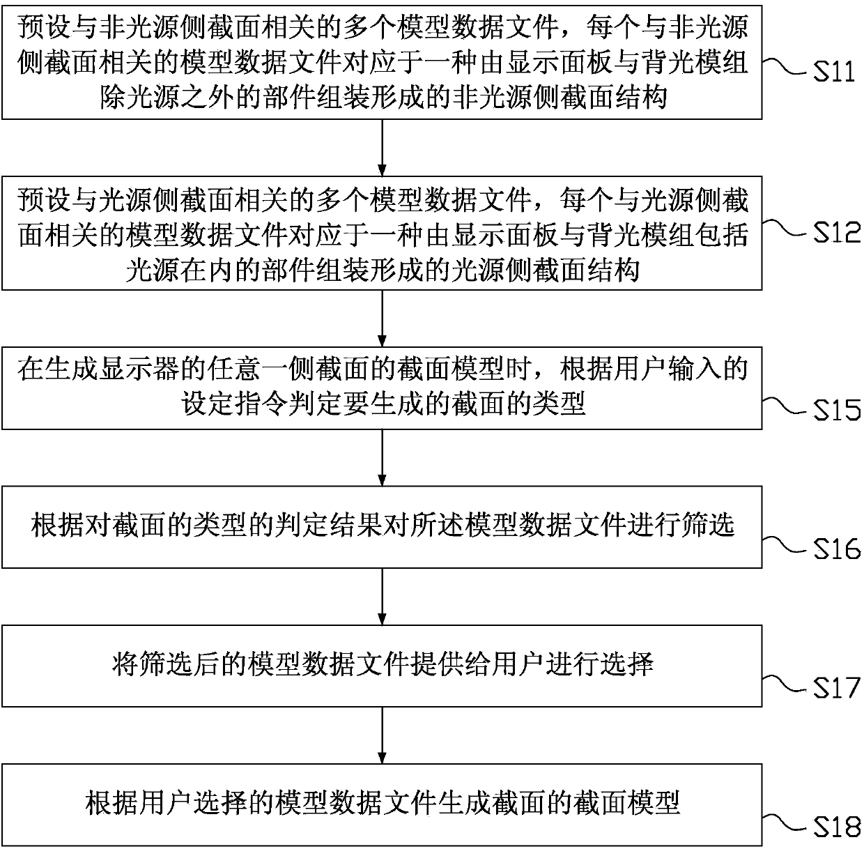
[0064] image 3 It is a flow chart of a method for generating a sectional model of a display using a computer graphics system in the first embodiment of the present invention, and the method includes:
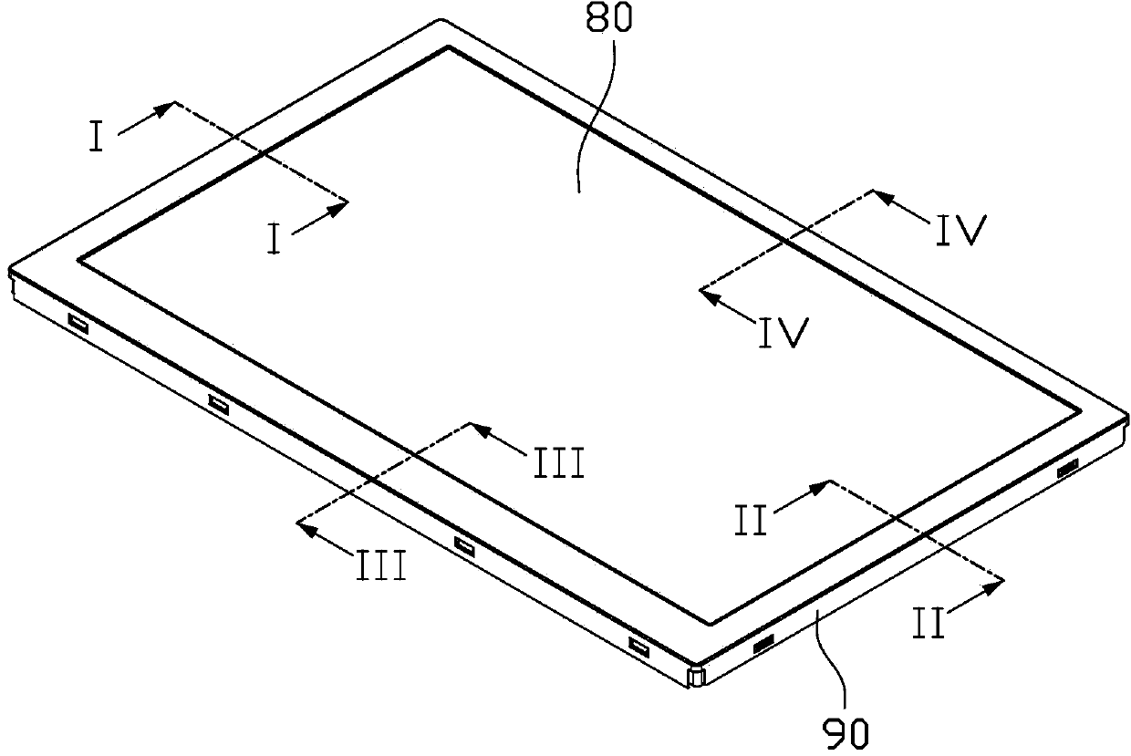
[0065] Step S11: preset a plurality of model data files related to the non-light source side section, and each model data file related to the non-light source side section corresponds to a display panel formed by assembling components of the backlight module except the light source Non-light source side cross-sectional structure.
[0066] In the computer drawing system, with the help of the secondary development tool of the drawing software, through the programming language that can be used for secondary development, after compiling and compiling the program code, multiple models related to the side section of the non-light source can be established in the drawing system Data files, each model data file related to the non-light source side cross-section corresponds to a non-li...
no. 2 example
[0125] Figure 11 It is a flowchart of a method for generating a cross-sectional model of a display using a computer graphics system in the second embodiment of the present invention, the method comprising:
[0126] Step S21: preset a plurality of model data files related to the non-light source side section, each model data file related to the non-light source side section corresponds to a display panel formed by assembling components of the backlight module except the light source Non-light source side cross-sectional structure. For the specific content of this step, reference may be made to step S11 in the above-mentioned first embodiment, which will not be repeated here.
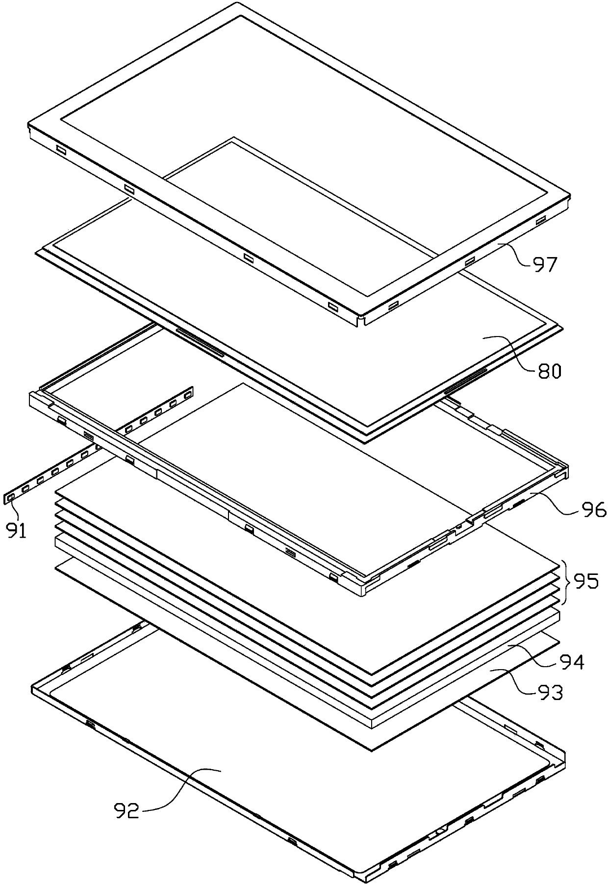
[0127] Step S22: preset a plurality of model data files related to the side section of the light source, each model data file related to the side section of the light source corresponds to a light source side formed by assembling the display panel and the backlight module including the light source cro...
PUM
 Abstract
Description
Claims
Application Information
 - Generate Ideas
- Intellectual Property
- Life Sciences
- Materials
- Tech Scout
- Unparalleled Data Quality
- Higher Quality Content
- 60% Fewer Hallucinations
Browse by: Latest US Patents, China's latest patents, Technical Efficacy Thesaurus, Application Domain, Technology Topic, Popular Technical Reports.
© 2025 PatSnap. All rights reserved.Legal|Privacy policy|Modern Slavery Act Transparency Statement|Sitemap|About US| Contact US: help@patsnap.com