Demonstration device of operating principle of hydraulic system

A technology of working principle and hydraulic system, applied in educational appliances, instruments, teaching models, etc., can solve problems such as difficulty in understanding the working principle of hydraulic system, and achieve the effect of simple structure, compactness and convenience

Inactive Publication Date: 2014-12-10
TANGSHAN COLLEGE
View PDF9 Cites 4 Cited by
  • Summary
  • Abstract
  • Description
  • Claims
  • Application Information

AI Technical Summary

Problems solved by technology

At present, there is no demonstration operation device for the working principle of the hydraulic system. T

Method used


Image

  • Demonstration device of operating principle of hydraulic system
  • Demonstration device of operating principle of hydraulic system
  • Demonstration device of operating principle of hydraulic system

Examples


Example Embodiment

[0034] A device for demonstrating the working principle of a hydraulic system of the present invention will be described in detail below in conjunction with the embodiments and drawings.

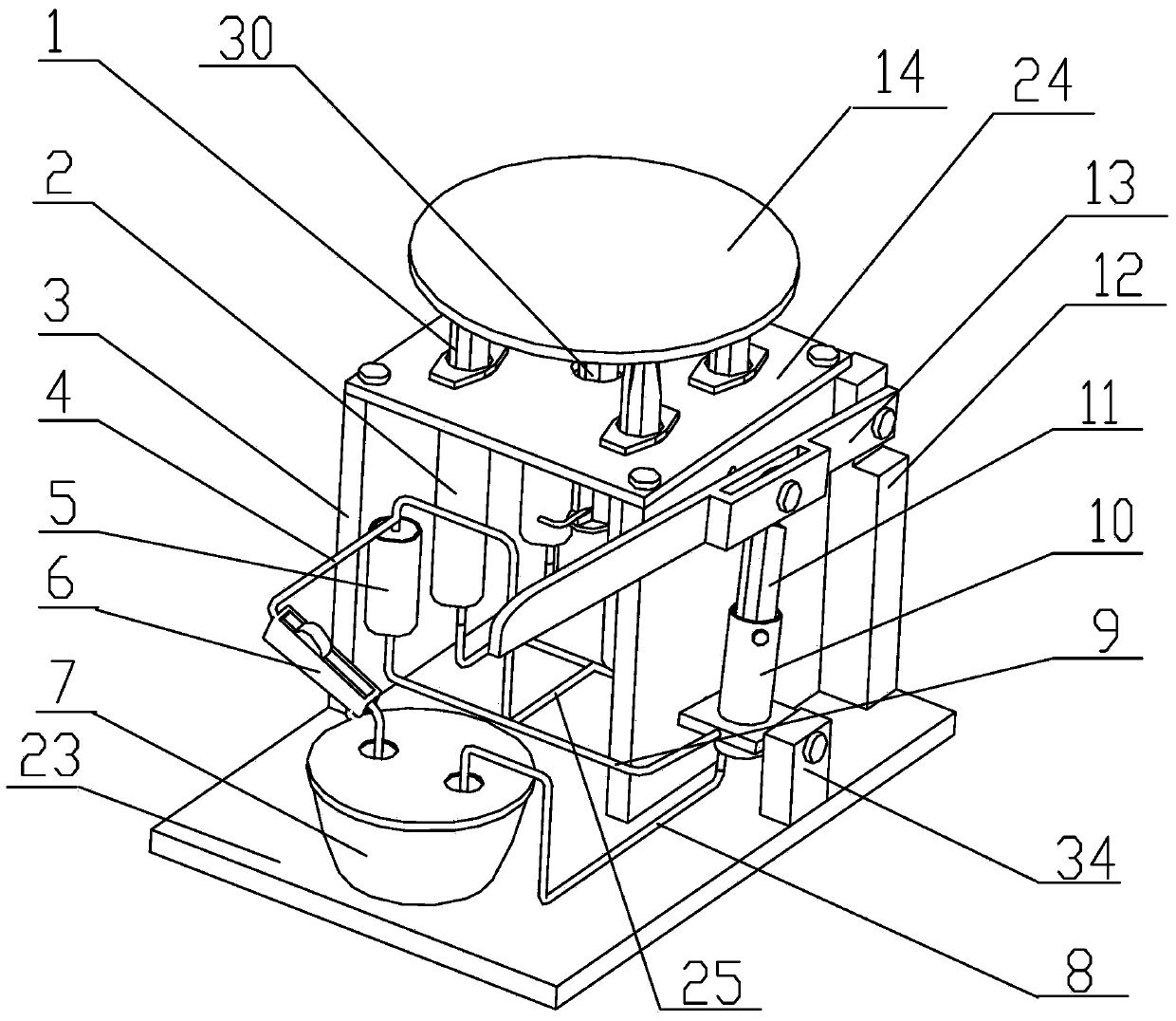
[0035] like figure 1 As shown, a hydraulic system working principle demonstration device of the present invention includes a base 23, which is arranged on the base 23 by the plexiglass side panels 3 vertically arranged on both sides and the plexiglass side panels 3 fixed on both sides. The lifting cylinder support formed by the plexiglass top plate 24, the lower end surface of the plexiglass top plate 24 is fixedly provided with four lifting hydraulic cylinders 2 with the same structure, and the lifting cylinder pistons of the four lifting hydraulic cylinders 2 The rods 1 pass through the plexiglass top plate 24 respectively to connect and support the weight tray 14 above the plexiglass top plate 24, and the bottom surface of the weight tray 14 is connected with a set of penetrating through ...


PUM


Abstract

Disclosed is a demonstration device of the operating principle of a hydraulic system. The demonstration device comprises a base, and a lifting cylinder support composed of organic glass side plates on two sides and an organic glass top plate. The organic glass side plates on two sides are arranged on the base, and the organic glass top plate is lapped on the organic glass side plates on two sides, four lifting hydraulic cylinders identical in structure are fixed on the lower end face of the organic glass top plate, lifting cylinder piston rods of the lifting hydraulic cylinders penetrate the organic glass top plate respectively to be connected with a weight tray arranged on the organic glass top plate, the bottom surface of the weight tray is connected with limit parts penetrating the organic glass top plate, the lifting hydraulic cylinders are communicated with a flow distribution cylinder through a flow distribution pipe connected at the bottom of the flow distribution cylinder, the flow distribution cylinder is communicated with a pump cylinder fixed on the base through an oil pressurizing pipe connected at the bottom of the pump cylinder, an oil suction port of the pump cylinder is communicated with a container arranged on the base through an oil suction port, the top end of a pump cylinder piston rod of the pump cylinder is hinged to a lever handle, one end of the lever handle is hinged to a lever support plate, and the lever support plate is fixed on the base. The demonstration device is simple in structure, small, convenient and capable of clearly demonstrating the operating principle of the hydraulic system for students.

Description

technical field [0001] The invention relates to a teaching demonstration device. In particular, it relates to a demonstration device for the working principle of a hydraulic system. Background technique [0002] The hydraulic system principle demonstration device is suitable for the demonstration of the working principle of the hydraulic system. The working principle of the hydraulic system is difficult to understand based on conventional theoretical explanations, and the experimental bench that is often used for auxiliary teaching is too large to be suitable for classroom teaching. In view of the above reasons, it is necessary to design a portable demonstration console for the working principle of the hydraulic system. very necessary. At present, there is no demonstration operation device for the working principle of the hydraulic system. Therefore, it is difficult to understand the working principle of the hydraulic system in classroom teaching. Contents of the inventi...

Claims


Application Information

Patent Timeline
IPC IPC(8): G09B25/02
Inventor 王杰
Owner TANGSHAN COLLEGE
Why Eureka
Try Eureka