
A Design Method for Distributed Grounding Electrode Used in HVDC Transmission System

A technology of distributed grounding pole and power transmission system, applied in the direction of DC network circuit devices, electrical components, circuit devices, etc., can solve the problem that the transformer cannot take measures in advance, DC bias loss, and does not consider the impact of DC incoming ground current on the AC power grid. degree and other issues, to achieve the effect of reducing the risk of DC bias, reducing harm, and eliminating losses

Active Publication Date: 2016-04-06
STATE GRID CORP OF CHINA +2
View PDF4 Cites 0 Cited by
  • Summary
  • Abstract
  • Description
  • Claims
  • Application Information

AI Technical Summary

Problems solved by technology

[0004] However, the site selection of traditional distributed grounding poles does not consider the degree of influence of the DC current into the ground on the AC grid, so that it is impossible to predict the risk of DC bias of each transformer in the AC grid, resulting in the inability to predict the risk of DC bias for transformers with a high risk of DC bias. Take measures, which will lead to losses due to DC bias problems after the new grounding pole is put into operation

Method used

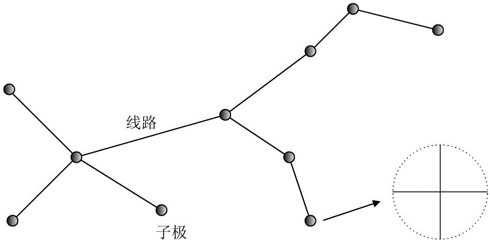

Image

  • A Design Method for Distributed Grounding Electrode Used in HVDC Transmission System
  • A Design Method for Distributed Grounding Electrode Used in HVDC Transmission System
  • A Design Method for Distributed Grounding Electrode Used in HVDC Transmission System

Examples


Embodiment Construction

[0029] The technical solutions in the present invention will be clearly and completely described below in conjunction with the accompanying drawings in the present invention.

[0030] The invention provides a design method for a distributed grounding electrode used in a high-voltage direct current transmission system, which includes the following steps:

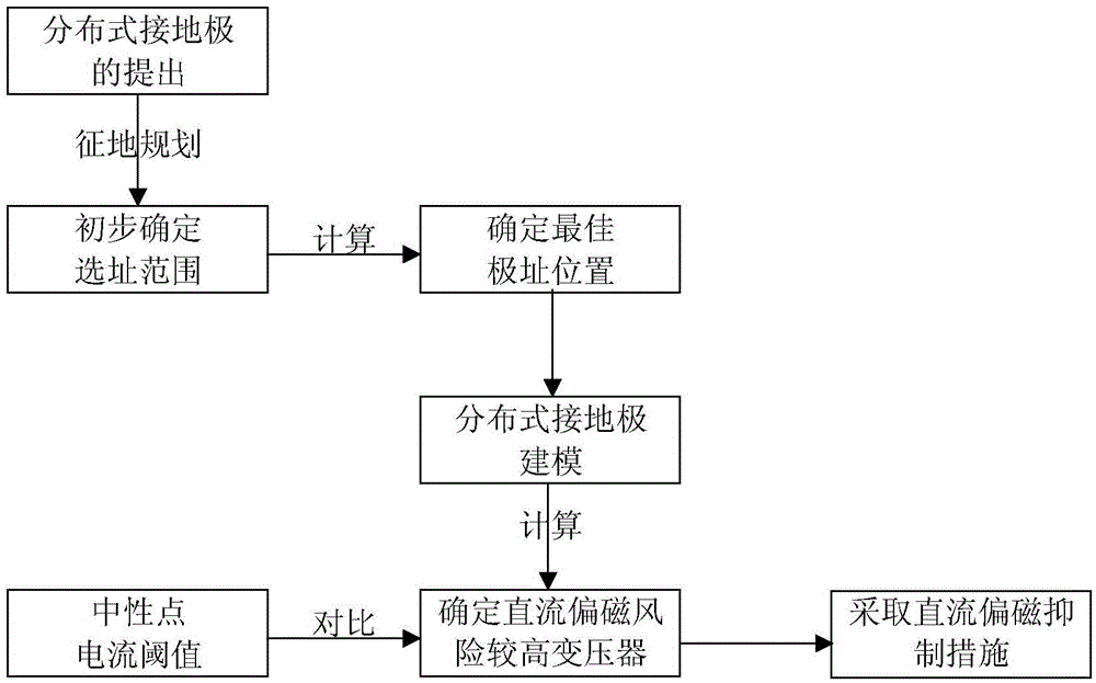
[0031] Step 1. Preliminarily select the scope of the new grounding electrode according to the planning and land acquisition, and determine the best position of the new grounding electrode through the global optimal position variation particle swarm optimization algorithm.

[0032] Specifically, Step 1 is as follows:

[0033] a. Define the objective function, the minimum average value of the transformer magnetomotive force in the system, the minimum average neutral point current of the transformer or the minimum maximum neutral point current of the transformer can be used as the objective function. The independent variable p=...


PUM


Abstract

Disclosed is a distributed grounding electrode design method for a high-voltage direct-current transmission system. The distributed grounding electrode design method includes the steps of 1), preliminarily selecting the scope for grounding electrodes to be established according to planning and land expropriation, and determining the best position for the grounding electrodes to be established through a global optimal position mutation particle swam optimization algorithm; 2), determining the biggest potential rise of sub-electrodes according to temperature rise of the grounding electrodes and checking step potential; 3), connecting all the grounding electrodes with newly established sub-electrodes through an overhead line; 4), establishing a unified model for the distributed grounding electrodes and direct-current distribution of a alternating-current network; 5), according to the solved direct-current distribution of the alternating-current network, predicting risks of direct-current magnetic bias occurring to transformers of the alternating-current network; 6), for the transformers with the risks of direct-current magnetic bias in prediction, taking measures to restrain or eliminate negative influence brought by the problem of the direct-current magnetic bias. By the distributed grounding electrode design method, the risks of the direct-current magnetic bias can be reduced, and the degree of the direct-current magnetic bias after establishment of the grounding electrode can be estimated, so that damage brought by the direct-current magnetic bias can be reduced.

Description

technical field [0001] The invention relates to the field of high-voltage direct current transmission engineering design, in particular to a design method for distributed grounding electrodes of a high-voltage direct current transmission system. Background technique [0002] At present, my country's receiving end converter stations are often located in economically developed areas, where the population density is high, the grid structure is huge and complex, and there are many underground metal facilities (such as oil and gas transmission and water supply pipelines, etc.), which makes the traditional conventional grounding electrode Under the design mode, the site selection of DC grounding electrode becomes more and more difficult. At the same time, with the massive operation of large-capacity UHV DC transmission projects, the problems of electromagnetic compatibility caused by the DC transmission ground current and the harmonics of the converter station have become more prom...

Claims


Application Information

Patent Timeline
Patent Type & Authority Patents(China)
IPC IPC(8): H02J1/00
Inventor 阮羚周友斌潘卓洪李念李伟邓万婷杨琪徐碧川文习山鲁海亮
Owner STATE GRID CORP OF CHINA
Learn More