Anti-Potential Induced Degradation (PID) control method and control system
What is AI technical title?
AI technical title is built by PatSnap AI team. It summarizes the technical point description of the patent document.
A control method and technology for a control system, which are applied in the field of back-EMF-induced decay control methods and control systems, can solve problems such as reducing the life of a bias power supply, PID devices that cannot be turned on and off intelligently, and energy consumption.
Active Publication Date: 2014-12-10
SUNGROW POWER SUPPLY CO LTD
View PDF5 Cites 10 Cited by
Summary
Abstract
Description
Claims
Application Information
AI Technical Summary
This helps you quickly interpret patents by identifying the three key elements:
Problems solved by technology
Method used
Benefits of technology
Problems solved by technology
[0007] However, the existing technology still has the following disadvantages: the anti-PID device cannot be turned on and off intelligently, so that when the PID does not occur on the battery board, the bias power supply will always work and consume energy. Piezoelectric Lifetime
Method used
Image
Click on the blue label to locate the original text in one second.
Reading with bidirectional positioning of images and text.
Examples
Embodiment 1
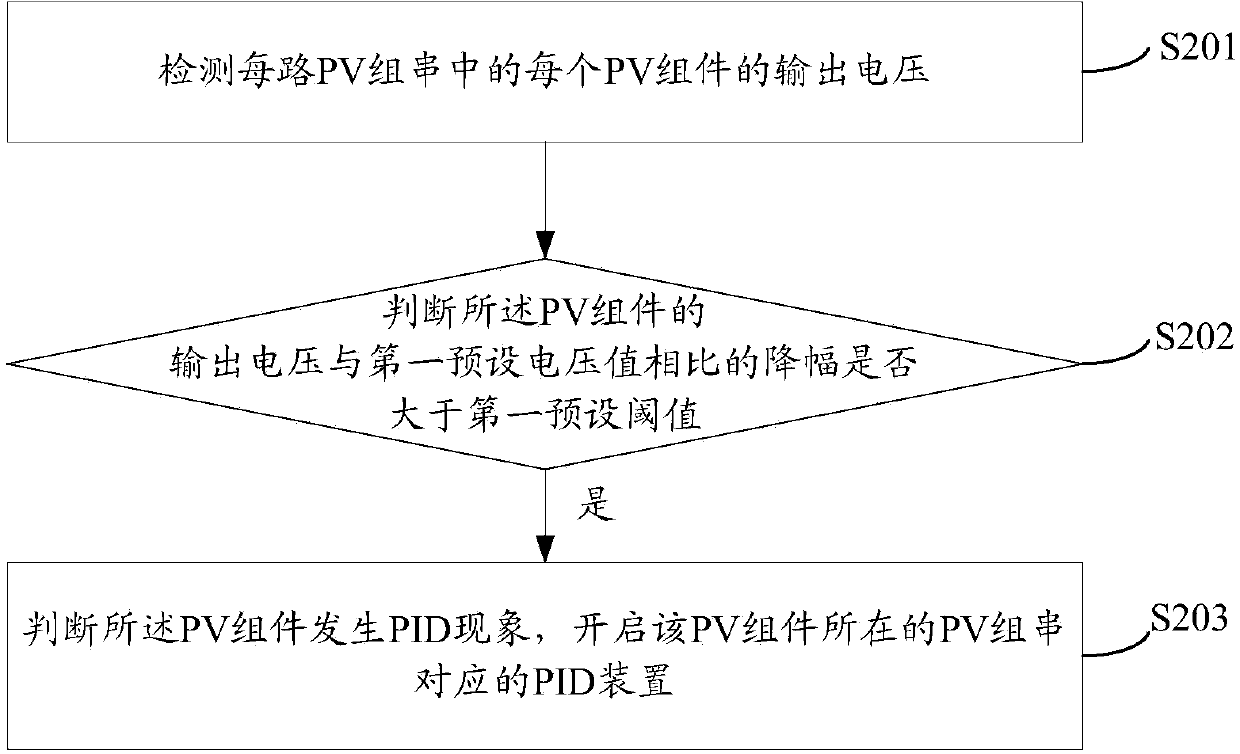
[0055] see figure 2 , which is a flow chart of Embodiment 1 of the method for controlling back EMF-induced decay provided by the present invention.
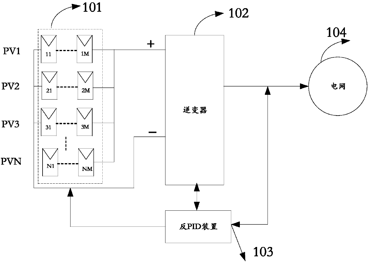
[0056] A method for controlling back-emf-induced attenuation provided in this embodiment is applied in a photovoltaic power generationsystem, where each PV string includes M PV modules connected in series; each PV string is configured with a back-emf-induced attenuation PID device;
[0057] Include the following steps:
[0058] S201: Detect the output voltage of each PV module in each PV string;
[0059] It should be noted that each PV module refers to each panel, that is, a PV string includes multiple panels connected in series.
[0060] In this embodiment, it is necessary to detect the output voltage of each battery board, so that it can be accurately judged whether to turn on the PID device. The battery board at the negative pole of the DC side is prone to PID phenomenon.
[0061] If the output voltage of the entire PV s...
Embodiment 2
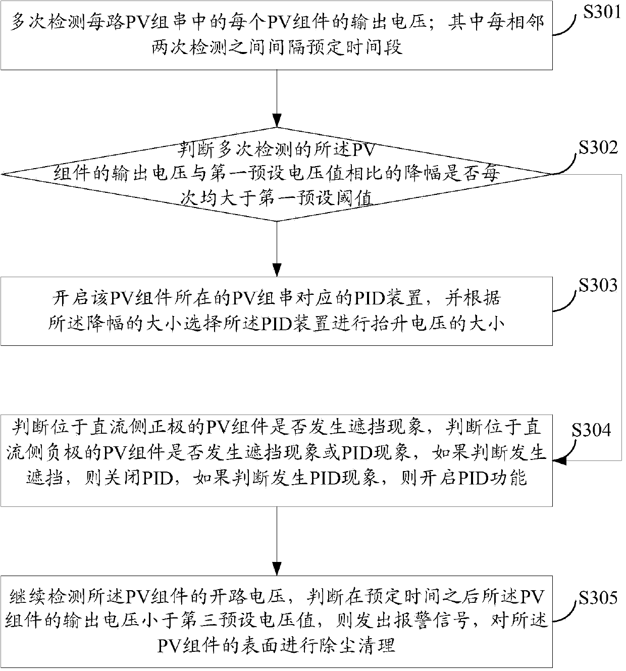
[0067] see image 3 , which is a flow chart of Embodiment 2 of the method for controlling back EMF-induced decay provided by the present invention.
[0068] S301: Detect the output voltage of each PV module in each PV string multiple times; wherein a predetermined period of time is separated between two adjacent detections.
[0069] It should be noted that, in order to accurately determine whether the PID phenomenon occurs, multiple detections can be performed in this embodiment, for example, the predetermined time interval is 1 day, and of course it can also be an integer multiple or a decimal multiple of 1 day, for example, 2 days, 0.5 days, or 1.5 days etc.
[0070] S302: Determine whether the output voltage of the PV module detected multiple times has a drop range greater than a first preset threshold each time compared with a first preset voltage value. If yes, execute S303, and if no, execute S304.
[0071] For example, sometimes the battery panel is blocked, and the ...
PUM
Abstract
The invention provides an anti-Potential Induced Degradation (PID) control method and a control system and is applied to photovoltaic generating systems. Each PV serial string comprises PV components connected in series, with the number of the components as M, and is equipped with an anti-PID device. The anti-PID control method comprises the following steps: detecting the output voltage of each PV component of each PV series string; judging whether the decreasing amplitude of the output voltage of each PV component relative to a first preset voltage value, is greater than a first preset threshold value or not; if the output voltage of the PV component is greater than the first preset threshold value, determining that a PID phenomenon occurs in one of the PV components, and then starting the PID device corresponding to the PV serial string where the PV component is located. The output voltage decreasing amplitude of each PV component in each PV series string can be precisely detected and when the decreasing amplitude exceeds the first preset threshold value, the PID phenomenon occurs and the corresponding PID device is started. Through the adoption of the control method, the PID devices of all serial strings can be accurately controlled to operate and the anti-PID function can be achieved; as one PID device does not serve for all the PV serial strings, each PV serial string can be precisely controlled.
Description
technical field [0001] The invention relates to the technical field of photovoltaic power generation equipment, in particular to a control method and a control system for counter electromotive force-induced attenuation. Background technique [0002] Potential Induced Degradation (PID, Potential Induced Degradation): It is a phenomenon in which the performance of components is reduced due to the high voltage applied to the ground. The high voltage can be positive or negative depending on the characteristics of the battery board. The performance degradation of the module is manifested as a decrease in the open circuit voltage (Voc) and a decrease in the fill factor (FF). This phenomenon can be recovered under the reverse pressure. [0003] At present, in order to suppress the PID effect of the battery board, there are two main anti-PID technologies adopted at home and abroad: [0004] The first is to indirectly raise the voltage of the negative electrode PV- of the battery pa...
Claims
Application Information
Patent Timeline
Application Date:The date an application was filed.
Publication Date:The date a patent or application was officially published.
First Publication Date:The earliest publication date of a patent with the same application number.
Issue Date:Publication date of the patent grant document.
PCT Entry Date:The Entry date of PCT National Phase.
Estimated Expiry Date:The statutory expiry date of a patent right according to the Patent Law, and it is the longest term of protection that the patent right can achieve without the termination of the patent right due to other reasons(Term extension factor has been taken into account ).
Invalid Date:Actual expiry date is based on effective date or publication date of legal transaction data of invalid patent.

