Method and device for deinterlacing

A technology for deinterlacing and vertical direction, which is applied in the field of deinterlacing and deinterlacing, which can solve the problems of pushing up the implementation cost of deinterlacing method, large amount of calculation, and high hardware requirements, so as to avoid sawtooth and reduce the amount of calculation. Small, good image quality results

Active Publication Date: 2014-12-10
APPOTECH
View PDF11 Cites 7 Cited by
  • Summary
  • Abstract
  • Description
  • Claims
  • Application Information

AI Technical Summary

Problems solved by technology

[0008] For some images that move very fast, the difference between the pixels of the interpolation points in the front and back fields is often very small, so the traditional three-field detection is easy to misjudge it as still
Therefore, people improve the traditional three-field motion detection method. For example, the invention patents of CN101600061B and CN1207906C disclose two different de-interlacing methods based on the three-field motion detection method. Although these methods have improved the three-field motion detection performance, but its computational complexity is huge, and the hardware requirements are too high, which also pushes up the implementation cost of the deinterlacing method

Method used


Image

  • Method and device for deinterlacing
  • Method and device for deinterlacing
  • Method and device for deinterlacing

Examples


Embodiment Construction

[0025] The de-interlacing method of the present invention is applied in digital broadcasting and television transmission technology, and is used for converting interlaced data into progressive scanning technology, that is, generating pixel values ​​of a row of missing pixels in each field. The de-interlacing device of the present invention is a device for converting interlaced data into progressive data by using a de-interlacing method.

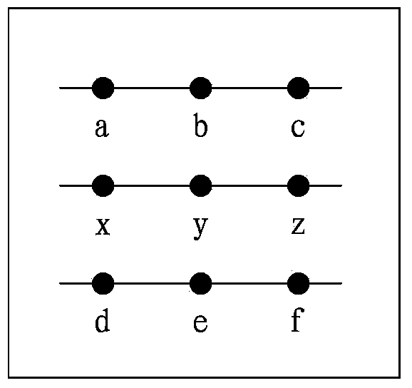
[0026] Data transmitted by interlaced scanning technology such as figure 2As shown, there are a plurality of adjacent fields, and each field only contains odd-numbered or even-numbered rows of data. For example, three adjacent fields are the previous field F(n-1), the current field F(n), and the subsequent field F(n+1), and the current field F(n) is a field undergoing deinterlacing, Pixel points a, b, c and pixel points d, e, f are pixels of even rows adjacent to the current field F(n), and pixels of odd rows are missing between two rows of...


PUM


Abstract

The invention provides a method and device for deinterlacing. The method comprises the following steps: using difference values between pixels, corresponding to the pixel for interpolation, in the previous field and the subsequent field and the pixel values, corresponding to the next pixel for interpolation, in the previous field and the subsequent field, as well as the movement weight value of the previous interpolation pixel to calculate the movement weight value of the pixel for interpolation to calculate the inter-field interpolation and the in-field interpolation of the pixel for interpolation; using the inter-field interpolation, the in-field interpolation and the movement weight value of the pixel for interpolation to calculate the initial pixel value of the pixel for interpolation; calculating the relativity of the current field in multiple directions according to the difference values among the pixel values of the pixels in multiple directions in the current field; selecting multiple pixels in the direction with the maximal relativity and the pixel value of the pixel corresponding to the pixel for interpolation in the previous field for filtering; calculating the compensation pixel value, and calculating the determined pixel value of the pixel for interpolation according to the initial pixel value, the compensation pixel value and the in-field interpolation. The device is used for realizing deinterlacing by adopting the method. The device for deinterlacing is small in amount of calculation, lower in requirement on a hardware device and good in output picture quality.

Description

technical field [0001] The invention relates to the field of video signal processing, in particular to a de-interlacing method for converting interlaced scanning into progressive scanning and a device for realizing the method. Background technique [0002] Digital broadcasting and television technology needs to transmit video signals in the form of data frames, and the transmitted data often includes multiple lines of data. The digital broadcast TV technology includes progressive scanning technology and interlaced scanning technology, such as figure 1 As shown, the data transmitted by the progressive scanning technology contains the data of each line, such as figure 1 Shown are the three rows of data, the first row of data includes three pixels a, b, c, the second row includes three pixels x, y, z, the third row includes three pixels d, e, f. For example, each field of data transmitted by digital broadcasting and television technology includes the data of each line, and t...

Claims


Application Information

Patent Timeline
Patent Type & Authority Applications(China)
IPC IPC(8): H04N7/01
Inventor 陈文捷
Owner APPOTECH
Why Eureka
Try Eureka