Internal over-voltage protection LED driver, internal over-voltage protection LED driving circuit and LED driver working method

A technology of LED driver and overvoltage protection, which is applied in the direction of lamp circuit layout, electric light source, lighting device, etc., can solve problems such as fluctuations, and achieve the effect of simplified peripheral circuits and good reliability

Inactive Publication Date: 2014-12-10
CHANGZHOU TOPIC SEMICON TECH
View PDF3 Cites 1 Cited by
  • Summary
  • Abstract
  • Description
  • Claims
  • Application Information

AI Technical Summary

Problems solved by technology

[0002] The non-isolated driver chips on the market, such as the driver chip R9128, adopt the indirect OVP (overvoltage protection) method; that is, after entering the overvoltage protection and open circuit protection, the hiccup mode is used to restart continuously, and the driving voltage is less than 7V. VCC voltage will fluctuate with different loads

Method used


Image

  • Internal over-voltage protection LED driver, internal over-voltage protection LED driving circuit and LED driver working method
  • Internal over-voltage protection LED driver, internal over-voltage protection LED driving circuit and LED driver working method
  • Internal over-voltage protection LED driver, internal over-voltage protection LED driving circuit and LED driver working method

Examples


Embodiment 1

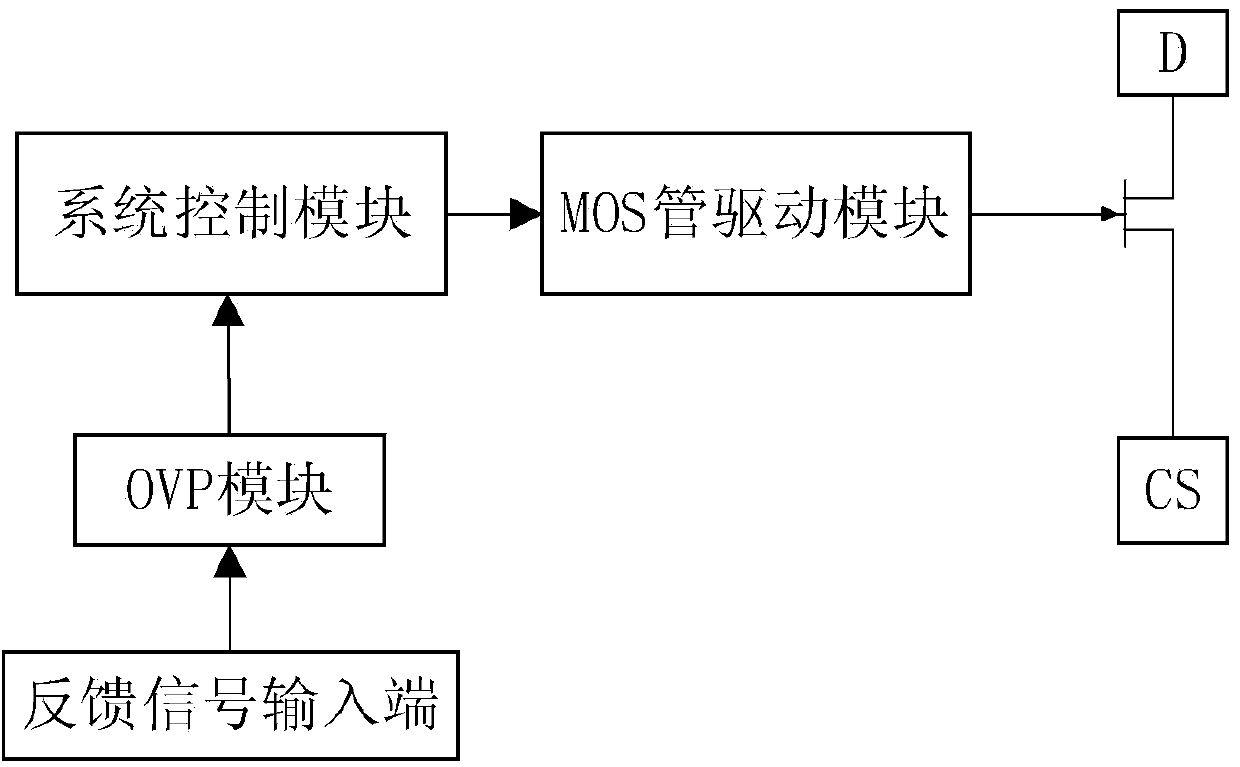
[0025] figure 1 A block diagram of the LED driver is shown.

[0026] Such as figure 1 As shown, an LED driver with built-in overvoltage protection, including:

[0027] The feedback signal input terminal ZCD collects the output voltage of the LED driving circuit formed by the LED driver U1.

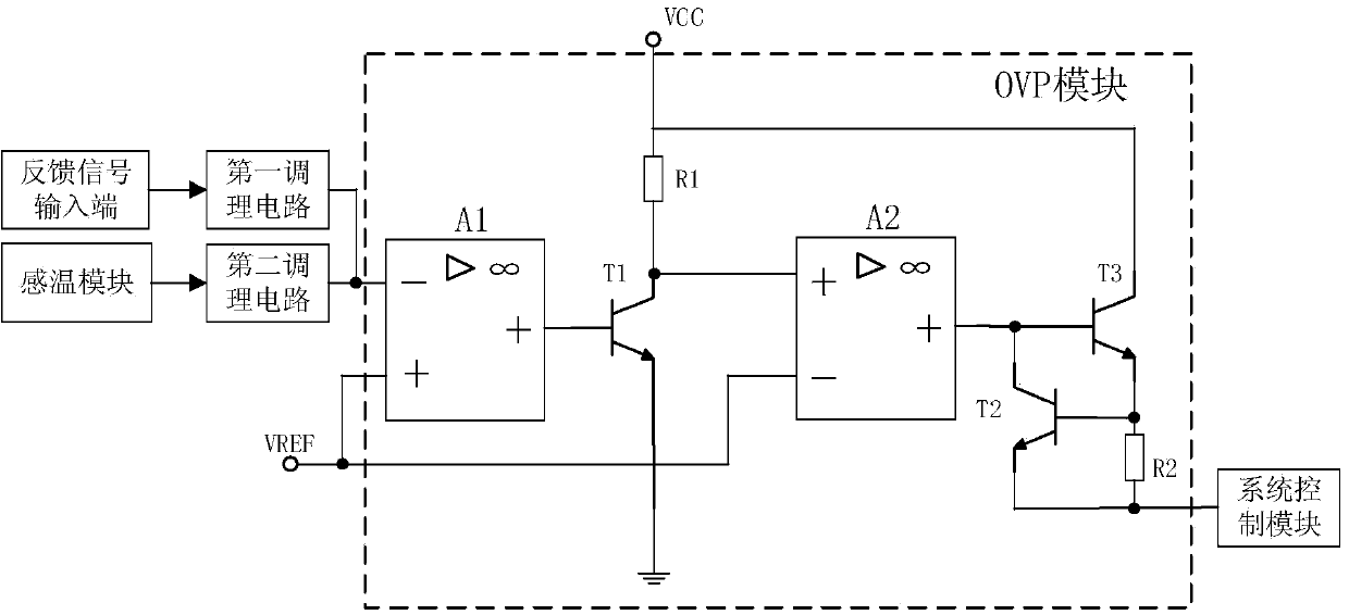
[0028] The OVP module judges whether to output an overvoltage protection signal according to the obtained output voltage. Specifically, the output voltage is compared with the overvoltage protection reference voltage UREF, and if the output voltage is greater than the overvoltage protection reference voltage, an overvoltage protection signal is output. The OVP module is an overvoltage protection module.

[0029] A system control module, configured to lock the LED driver according to the overvoltage protection signal.

[0030] Wherein, the system control module can be realized by a microprocessor. It can also be realized by using ST's STM8S series MCU. The locking of the LED driver m...

Embodiment 2

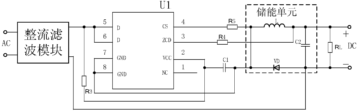
[0037] image 3 A circuit diagram of an LED driving circuit constituted by the LED driver is shown.

[0038] Among them, the pins of the LED driver U1: pin 1 floating, pin 2 power supply, pin 3 feedback signal input terminal, pin 4 MOS tube source, pin 5 and pin MOS tube drain, pin 7 and pin 8 grounding terminal .

[0039] Such as image 3 As shown, in the LED driving circuit composed of the LED driver based on Embodiment 1, the output terminal of the LED driver is connected to the energy storage unit through an output resistor R5, and the output terminal of the energy storage unit is connected through a feedback resistor R4 is connected with the feedback signal input terminal (pin 3).

[0040] Wherein, the energy storage unit includes: an inductor L, a capacitor C2, and a freewheeling tube VD.

[0041] The LED driver realizes the feedback function only through the feedback resistor R4, which is simpler than the circuit of the traditional LED driver circuit and saves hardw...

Embodiment 3

[0043] The working method of the LED driver based on Embodiment 1, the working method includes: an overvoltage protection method, the method includes:

[0044] The OVP module judges whether to output an overvoltage protection signal according to the obtained output voltage; if the output voltage is greater than the overvoltage protection reference voltage UREF, then outputs an overvoltage protection signal, and the system control module outputs the overvoltage protection signal according to the overvoltage protection signal The LED driver is locked out.

[0045] In this embodiment, the specific implementation of the OVP module is the same as that in Embodiment 1, and will not be repeated here.

[0046] Further, the working method also includes: a method for overheating protection, which includes: converting the temperature signal into a voltage signal through a temperature sensing module and then inputting it to the OVP module through a second conditioning circuit, and the sec...


PUM


Abstract

The invention relates to an internal over-voltage protection LED driver, an internal over-voltage protection LED driving circuit and an LED driver working method. The LED diver comprises a feedback signal input end, an OVP (over-voltage protection) module and a system control module, the feedback signal input end collects output voltage of the LED driving circuit composed of the LED driver, the OVP module judges whether or not to output an over-voltage protection signal according to the acquired output voltage, and the system control module is used for locking the LED driver according to the over-voltage protection signal. A peripheral circuit of the LED driving circuit is simpler and better in reliability through internal over-voltage protection; besides, the hiccup condition of the LED driver can be avoided, and when output voltage is higher than over-voltage protection reference voltage, the LED driver is directly locked to be further protected.

Description

technical field [0001] The invention relates to an LED driving power supply, in particular to an LED driver with built-in overvoltage protection, a driving circuit and a working method of the LED driver. Background technique [0002] The non-isolated driver chips on the market, such as the driver chip R9128, adopt the indirect OVP (overvoltage protection) method; that is, after entering the overvoltage protection and open circuit protection, the hiccup mode is used to restart continuously, and the driving voltage is less than 7V. The VCC voltage will fluctuate with different loads. [0003] Therefore, in order to overcome the above defects, it is a technical problem in the art to design a highly integrated LED driver with built-in overvoltage protection. Contents of the invention [0004] The object of the present invention is to provide an LED driver with built-in overvoltage protection, which integrates the overvoltage protection inside the LED driver, effectively reduc...

Claims


Application Information

Patent Timeline
Patent Type & Authority Applications(China)
IPC IPC(8): H05B37/02
Inventor 张永良
Owner CHANGZHOU TOPIC SEMICON TECH
Why Eureka
Try Eureka