Integration circuit and integration method thereof

A technology of integrating circuit and integrating method, applied in the field of integrating circuit and its integration, can solve the problems of high cost, complex peripheral circuit of the chip, and high failure risk, and can reduce the capacitance value, reduce the risk of failure, and simplify the peripheral circuit of the chip. Effect

Inactive Publication Date: 2020-06-23
CRM ICBG (WUXI) CO LTD
View PDF10 Cites 0 Cited by
  • Summary
  • Abstract
  • Description
  • Claims
  • Application Information

AI Technical Summary

Problems solved by technology

[0005] In view of the above-mentioned shortcomings of the prior art, the purpose of the present invention is to provide an integrating circuit and its integrating method, which are used to solve the problems of complex peripheral circuits, high cost, and high failure risk of the closed-loop control loop chip in the prior art.

Method used


Image

  • Integration circuit and integration method thereof
  • Integration circuit and integration method thereof
  • Integration circuit and integration method thereof

Examples


Embodiment 1

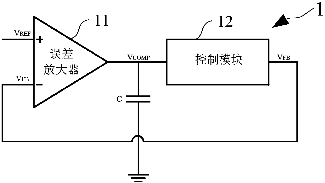
[0044] like figure 1 As shown, the present embodiment provides an integrating circuit 1, and the integrating circuit 1 includes:

[0045] An error amplifier 11 , a filter capacitor C and a control module 12 .

[0046] like figure 1 As shown, the non-inverting input terminal of the error amplifier 11 is connected to a reference voltage V REF , the inverting input terminal is connected to the output terminal of the control module 12 , and the output terminal of the error amplifier 11 is connected to the input terminal of the control module 12 . The upper plate of the filter capacitor C is connected to the output terminal of the error amplifier 11 , and the lower plate is grounded.

[0047] It should be noted that, in this embodiment, the error amplifier 11 and the control module 12 are integrated in the chip; the filter capacitor C is arranged outside the chip, and is connected to the error amplifier 11 and the The control module 12 is connected.

[0048] Specifically, the ...

Embodiment 2

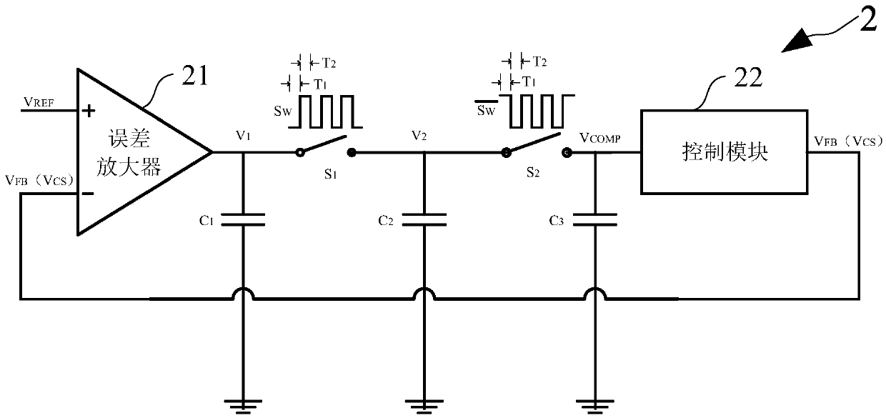
[0055] like image 3 As shown, the present embodiment provides an integrating circuit 2, and the integrating circuit 2 includes:

[0056] The error amplifier 21 , the first switch S1 , the second switch S2 , the first capacitor C1 , the second capacitor C2 , the third capacitor C3 and the control circuit 22 .

[0057] like image 3 As shown, the first input terminal of the error amplifier 21 is connected to the reference voltage V REF , the second input terminal is connected to the feedback voltage V FB , the error amplifier 21 calculates the reference voltage V REF with the feedback voltage V FB difference and amplify the output.

[0058] Specifically, in this embodiment, the non-inverting input terminal of the error amplifier 21 receives the reference voltage V REF , the inverting input receives the feedback voltage V FB , in practical applications, the input terminal of the error amplifier 21 can be interchangeably connected with the input signal, and the polarity of...


PUM


Abstract

The invention provides an integrating circuit and an integrating method thereof. The integrating circuit comprises: an error amplifier for amplifying and outputting a difference value between a reference voltage and a feedback voltage; a first switch and a second switch which are sequentially connected to the output end of the error amplifier; a first capacitor connected between the output end ofthe error amplifier and the ground; a second capacitor connected between the output end of the first switch and the ground; a third capacitor connected between the output end of the second switch andthe ground, wherein switching signals of the first switch and the second switch are opposite in phase. The difference between the reference voltage and the feedback voltage is amplified to obtain an error voltage, the error voltage is filtered to generate a compensation voltage, the compensation voltage is processed by the control module to generate a feedback voltage, a feedback loop is formed, loop integration is further realized, and the mean value of the feedback voltage is equal to the reference voltage value. The integrating circuit is simple in structure and high in integration level, alarge filter capacitor can be omitted, a peripheral circuit is simplified, the system cost is reduced, and the failure problem caused by the peripheral filter capacitor is thoroughly eliminated.

Description

technical field [0001] The invention relates to the field of integrated circuit design, in particular to an integrating circuit and an integrating method thereof. Background technique [0002] With the continuous upgrading of LED drive circuits, the simplification of peripheral circuits, the low cost of the overall solution, and high reliability have become the direction and goal that everyone has unanimously recognized. In the field of LED driving technology, a closed-loop control loop is often required to stabilize the average value of the sampling voltage at the reference voltage value, so as to control the LED driving system to work stably with a preset output. [0003] The traditional closed-loop control loop needs to be connected to a filter capacitor with a large capacitance. Since the filter capacitor has a large capacitance, it cannot be integrated into the chip. Therefore, the filter capacitor needs to be set outside the chip. Therefore, it needs to be reserved on ...

Claims


Application Information

Patent Timeline
Patent Type & Authority Applications(China)
IPC IPC(8): G05F1/56
CPCG05F1/561G05F1/56
Inventor 张识博卢圣晟李亮
Owner CRM ICBG (WUXI) CO LTD
Why Eureka
Try Eureka