trajectory control device

A trajectory control and trajectory technology, which is applied in the field of trajectory control devices, can solve the problems of inconsistency and inconsistency in processing shapes, and achieve the effect of trajectory error suppression

Active Publication Date: 2017-05-10
MITSUBISHI ELECTRIC CORP
View PDF1 Cites 0 Cited by
  • Summary
  • Abstract
  • Description
  • Claims
  • Application Information

AI Technical Summary

Problems solved by technology

Usually, if a track error occurs, the processed shape will become inconsistent with the original shape, so it is not preferable

Method used


Image

  • trajectory control device
  • trajectory control device
  • trajectory control device

Examples


Embodiment approach 1

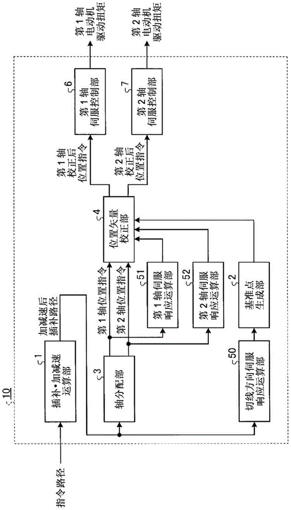
[0024] figure 1 It is a block diagram showing the configuration of the trajectory control device 10 according to Embodiment 1 of the present invention. The command path is supplied to the interpolation / acceleration / deceleration calculation unit 1 as coordinate values ​​on the trajectory of the trajectory of the movable part of the machine in the form of an NC program or the like. In addition, the interpolation method (straight line, arc, spline curve, etc.) between the commanded coordinate values ​​and the movement speed along the trajectory direction, that is, the feed speed, are also supplied to the interpolation and acceleration / deceleration calculations at the same time using NC programs. Department 1. In the interpolation / acceleration / deceleration calculation unit 1, by interpolating the commanded coordinate values ​​by the designated method, and performing acceleration along the command path with a separately designated predetermined acceleration or acceleration / decelerat...

Embodiment approach 2

[0063] Figure 5 It is a block diagram showing the structure of the trajectory control device 15 according to Embodiment 2 of the present invention. The difference from the first embodiment is that there are three movable axes of the machine, and servo control units (1st axis servo control unit 6, 2nd axis servo control unit 7, and 3rd axis servo control unit) are provided for each movable axis. Section 8) and a servo response computing unit (the first axis servo response computing unit 51, the second axis servo response computing unit 52, and the third axis servo response computing unit 53). The structure other than this is the same as that of the first embodiment.

[0064] In this embodiment, a machine having three movable axes of X-axis, Y-axis, and Z-axis is commanded including a three-dimensional shape. Set the X axis as the first axis, the Y axis as the second axis, and the Z axis as the third axis. The servo control unit (1st axis servo control unit 6, 2nd axis servo con...


PUM


Abstract

The trajectory control device of the present invention has: an interpolation / acceleration / deceleration calculation unit that interpolates a command path and obtains an interpolation path after acceleration and deceleration; The position command of the axis; the servo response calculation part, which calculates the servo response of the position command; the tangential direction servo response calculation part, which calculates the tangential direction servo response from the interpolation path after acceleration and deceleration; the reference point generation part, which calculates the tangential direction servo response A reference point is obtained in response; a position vector correction unit corrects the position command of each movable axis with a correction vector, and outputs a corrected position command of each movable axis; and a servo control unit outputs a motor drive torque to Each movable axis follows its corrected position command.

Description

Technical field [0001] The invention relates to a trajectory control device for suppressing trajectory errors and realizing high-speed and high-precision processing in control devices such as machine tools and laser processing machines. Background technique [0002] When a machine such as a machine tool or a laser processing machine is used for processing, control is performed so that the position of the processing tool relative to the workpiece follows the commanded path. This control is called trajectory control, and is usually realized by servo control so that the actual position of each movable axis of the machine follows the position command of each movable axis obtained from the command path. [0003] As a problem when performing trajectory control, there is a problem that the actual trajectory deviates from the commanded path due to the response delay of the control system of each movable axis. Generally, since each movable axis of the machine is controlled, errors caused b...

Claims


Application Information

Patent Timeline
Patent Type & Authority Patents(China)
IPC IPC(8): G05B19/404G05D3/12
CPCG05B19/404G05B2219/41189G05B2219/41194B23Q3/18G05B15/02
Inventor 长冈弘太朗
Owner MITSUBISHI ELECTRIC CORP
Why Eureka
Try Eureka