
Trajectory control device

A trajectory control and trajectory technology, applied in the field of trajectory control devices, can solve the problems of insufficient correction of trajectory errors and trajectory errors, and achieve the effects of improving trajectory accuracy, suppressing trajectory errors, and improving the quality of machined surfaces.

Active Publication Date: 2015-04-29
MITSUBISHI ELECTRIC CORP
View PDF6 Cites 0 Cited by
  • Summary
  • Abstract
  • Description
  • Claims
  • Application Information

AI Technical Summary

Problems solved by technology

[0007] However, in the method disclosed in the above-mentioned Patent Document 1, although the trajectory error can be effectively corrected when the same amount of trajectory error is stably generated as in a simple circle or an arc, when switching from a straight line to an arc In the case of such a command path, there is a problem that the trajectory error cannot be sufficiently corrected at the boundary portion, and the trajectory error remains in the corrected movement path.

Method used


Image

  • Trajectory control device
  • Trajectory control device
  • Trajectory control device

Examples


Embodiment approach 1

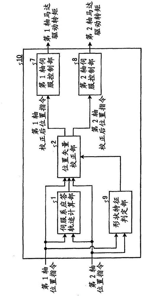
[0027] figure 1 It is a block diagram showing Embodiment 1 of the trajectory control device of the present invention. The trajectory control device 10 is configured to include a servo system response trajectory calculation unit 1 , a shape characteristic determination unit 9 , a position vector correction unit 2 , a first axis servo control unit 7 , and a second axis servo control unit 8 . The command path of the tool (blade object) is provided as the position command of the first axis and the second axis of the machine in the form of an NC program or the like. The servo system response trajectory calculation unit 1 calculates the response trajectory of the servo system when the first axis position command and the second axis position command are given. The calculation method of this response trajectory will be described later. The shape feature determination unit 9 determines whether the command path determined by the first axis and second axis position commands is a straig...

Embodiment approach 2

[0079] The structure of embodiment 2 is roughly the same as that of embodiment 1, and its structure is as follows figure 1 shown. The difference from the first embodiment is the method of determining the reference point and the correction vector in the correction vector calculation unit 3 . These differences will be described below.

[0080] The operation of the servo system response trajectory calculation unit 1 is the same as that of the first embodiment. In addition, in the operation of the position vector correcting unit 2 , the calculation of the trajectory error is the same as that of the first embodiment. Figure 7 It is a diagram showing the operation of the shape characteristic determination unit 9 according to the second embodiment. In this embodiment, the operation in the case of shifting from a circular arc to a straight line is assumed. Therefore, as the shape feature quantity (boundary point coordinates), the coordinate value of the junction of the arc and th...

Embodiment approach 3

[0089] The structure of embodiment 3 is roughly the same as that of embodiment 2, and its overall structure is as follows figure 1 shown. The difference from Embodiment 2 is the operation of the servo system response trajectory calculation unit. In addition, as the shape of the command path, consecutive circular arc commands with different orientations are given.

[0090] Figure 9 It is a figure explaining the operation|movement of the servo system response trajectory calculation part 1 in this Embodiment 3. In Embodiment 3, the response trajectory of the servo system is not obtained using a model of the servo system, but is obtained using only position command information. When the command shape is a smoothly changing shape such as an arc, there is a property that a trajectory error occurs in the acceleration direction of the command path in proportion to the magnitude of the acceleration. This proportionality factor is determined by the responsiveness of the servo syste...


PUM


Abstract

A trajectory control device controlling a trajectory of a movable portion includes a servo-system response-trajectory calculation unit that computes a servo-system response trajectory based on a position command of each movable axis, a shape-feature determination unit that outputs a shape feature amount including information of a position of a boundary point in a path shape and a running direction near the boundary point based on a determination from the position command whether the shape of the commanded path is straight or curved line, a position-vector correction unit that corrects a position vector based on the position command, the servo-system response trajectory and the shape feature amount, and outputs a corrected position command, and servo control units that control a motor of each movable axis by outputting a motor drive torque so that a position of each movable axis follows the corrected position command.

Description

technical field [0001] The present invention relates to a trajectory control device for managing tool trajectories in an NC control device for controlling NC machine tools, NC laser processing machines, etc., and particularly relates to a trajectory control device for suppressing trajectory errors and realizing high-speed and high-precision machining regardless of the shape of a command path . Background technique [0002] When processing is performed using a machine such as an NC machine tool or an NC laser processing machine, the position of the tool (blade such as an end mill) relative to the workpiece is controlled so that it follows a commanded path. This control is called trajectory control, and is generally performed by performing servo control so that the actual position of each movable axis of the machine follows the position command of each movable axis obtained from the command path. [0003] As a problem in trajectory control, there has been a conventional probl...

Claims


Application Information

Patent Timeline
Patent Type & Authority Patents(China)
IPC IPC(8): G05B19/404
CPCG05B19/19G05B2219/42342G05B2219/34135G05B19/4103G05B19/4097G05B19/41G11B19/28G05B19/416G05B19/404G05B13/02
Inventor 长冈弘太朗
Owner MITSUBISHI ELECTRIC CORP
Learn More