Low-modulus medical implant porous scaffold structure

A porous scaffold and low modulus technology, applied in scaffolds, bone implants, medical science, etc., can solve the problems of unsupported bone cells, complex processing technology of porous metal materials, doping, etc., to relieve pain and eliminate stress Blocking effect, effect of increasing service life

Active Publication Date: 2014-12-17
FUJIAN CTRUE MATERIALS TECH
View PDF7 Cites 13 Cited by
  • Summary
  • Abstract
  • Description
  • Claims
  • Application Information

AI Technical Summary

Problems solved by technology

However, in the prior art, the pore size and distribution of these metal porous materials are in a random state, which is different from the oriented bone tissue morphology of the human body; at the same time, the randomly distributed isotropic pores not only do not support the growth of bone cells and bone tissue, but also In terms of stress distribution, there is no distinction between the direction of large stress and the direction of small stress; in addition, these porous metal materials are complex in processing technology, often have internal defects, and may be doped with substances that are harmful to human health, etc.

Method used


Image

  • Low-modulus medical implant porous scaffold structure
  • Low-modulus medical implant porous scaffold structure
  • Low-modulus medical implant porous scaffold structure

Examples


Embodiment 1

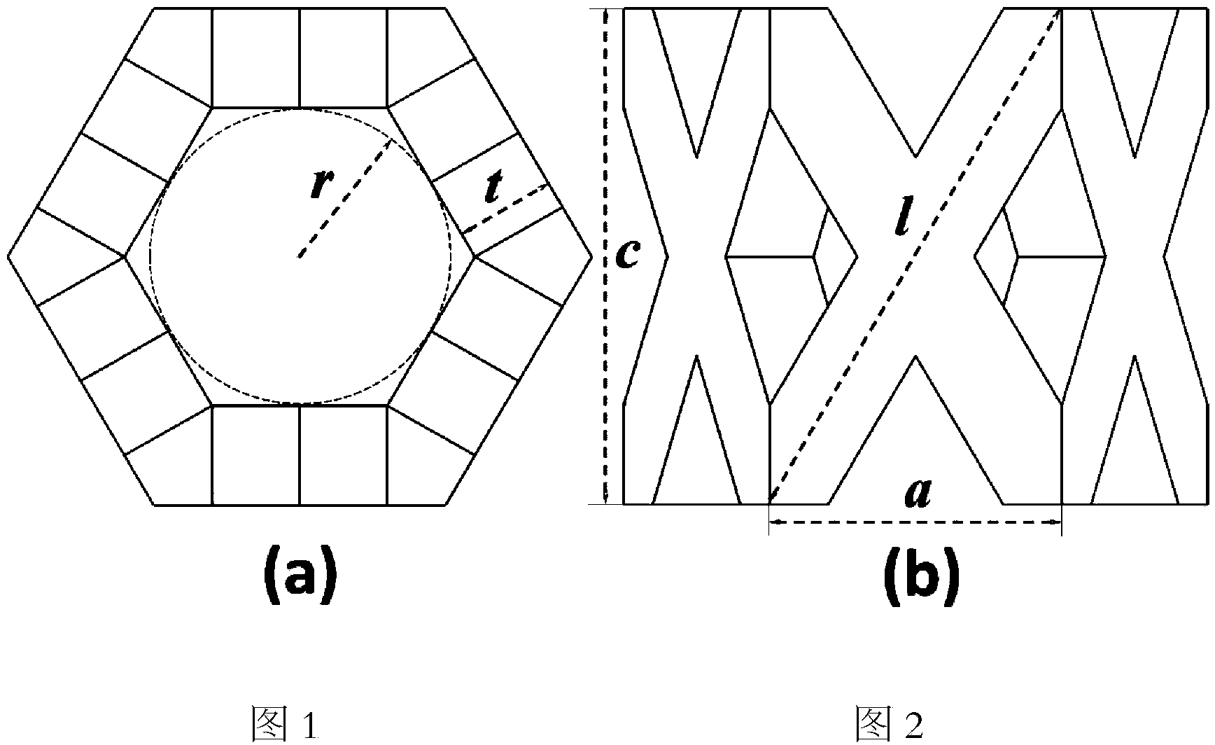
[0067] For the hexagonal prism basic unit, when the material of the implant is α-Ti (E=110GPa, ν=0.33), as image 3 Shown: The relationship between the relative modulus of the scaffold material and the relative density of the scaffold can be obtained by using the finite element method. The results showed that η 1 The value range is selected at 1.0-2.5, η 2 When the value range is selected to be 0.10-0.50, and the inscribed circle radius r of the through hole is selected to be in the range of 150 μm-750 μm, the relative modulus of the scaffold material will be lower than 30 GPa, which meets the range of human cortical bone modulus.

Embodiment 2

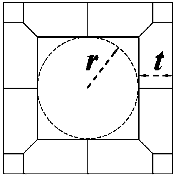
[0069] For the basic unit of quadrangular prism, when the material of the implant is α-Ti (E=110GPa, ν=0.33), as Figure 4 Shown: The relationship between the relative modulus of the scaffold material and the relative density of the scaffold can be obtained by using the finite element method. The results showed that η 1 The value range is selected at 1.0-2.5, η 2 When the value range is selected to be 0.1-0.35, and the radius r of the inscribed circle of the through hole is selected to be in the range of 150 μm-750 μm, the relative modulus of the scaffold material will be lower than 30 GPa, which meets the range of human cortical bone modulus.

[0070] Mg Example Group

Embodiment 3

[0072] For the basic unit of the hexagonal prism, when the material of the implant is Mg (E=44GPa, ν=0.26), as image 3 Shown: The relationship between the relative modulus of the scaffold material and the relative density of the scaffold can be obtained by using the finite element method. The results showed that η 1 The value range is selected from 1-2.5, η 2 When the value range is selected to be 0.1-0.5, and the radius r of the inscribed circle of the through hole is selected to be in the range of 150 μm-750 μm, the relative modulus of the scaffold material will be lower than 30 GPa, which meets the range of human cortical bone modulus.


PUM

PropertyMeasurementUnit
radiusaaaaaaaaaa

Abstract

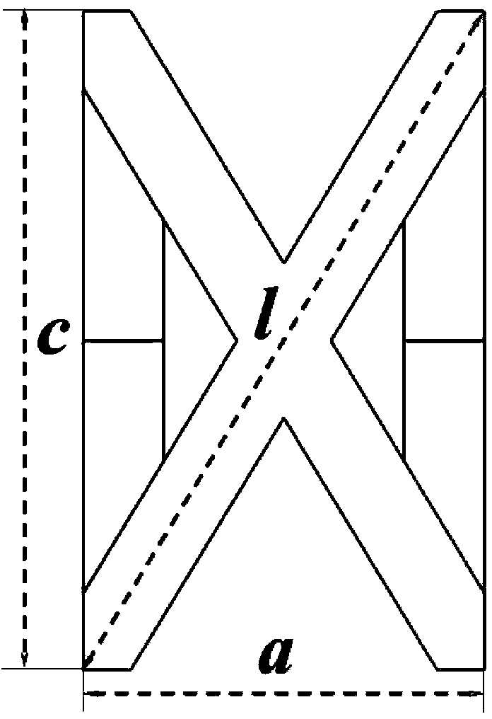
The invention relates to a porous scaffold structure, in particular to a low-modulus medical implant porous scaffold structure, and belongs to the field of medical implant material. The low-modulus medical implant porous scaffold structure is formed by sequentially overlaying a plurality of basic units in three-dimensional space along three-dimensional directions, wherein each basic unit comprises a quadruple prism body or a hexagonal prism body with a center communicating hole, formed by four or six side walls; each side wall adopts an X-shaped framework structure formed by intersecting two square ribs; the center communicating holes of each two adjacent basic units along the axis of the quadruple prism body or the hexagonal prism body are mutually communicated. The structure not only reduces the implant modulus, ensures that the implant modulus is perfectly matched with the implant strength, improves the configuration of a traditional metal implant, optimizes the mechanical distribution and reduces the stress shielding effect, but also has a regular through hole structures, is beneficial to the ingrowth of bone tissue, and can also enhance the mutual locking between the bone tissue and the implant, and shorten the rehabilitation time of patients.

Description

technical field [0001] The invention relates to a porous support structure, in particular to a low-modulus medical implant porous support structure, which belongs to the field of medical implant materials. Background technique [0002] In the field of treatment and repair of bone diseases such as fractures or osteonecrosis, especially in the treatment and repair of load-bearing bones, surgery to replace dead bones with implants is a common method to prevent further deterioration of bone diseases, avoid later fractures and even disability. Useful ways. At present, common implants mainly include autologous bone, allogeneic bone, bioceramics, organic polymers, degradable materials, and metal materials. Due to the disadvantages of pain at the donor site and limited sources of autologous bone grafting, the possibility of immune response and virus infection in allogeneic bone grafting, the inherent brittleness of bioceramics, the low strength of organic polymers, and the degradab...

Claims


Application Information

Patent Timeline
Patent Type & Authority Applications(China)
IPC IPC(8): A61L27/56A61F2/90
CPCA61L27/56A61F2/28A61F2310/00011A61F2310/00017A61F2310/00023A61F2310/00029A61F2310/00035A61F2310/00041A61F2310/00059A61F2310/00089A61F2310/00101A61F2310/00131A61F2310/00137A61F2310/00293A61L2430/02A61L27/50A61L27/04A61L27/045A61L27/042A61L27/06A61L27/12A61F2002/2835A61F2/3094A61F2002/30985A61F2002/30943A61L27/047
Inventor 林锦新吴松全林俊杰卢衍锦甘艺良赵超前
Owner FUJIAN CTRUE MATERIALS TECH
Why Eureka
Try Eureka