Air conditioner connecting pipe punching machine

A punching machine and air-conditioning technology, which is applied in the field of punching machines to achieve the effect of eliminating hidden safety hazards, good punching quality and safety assurance

Inactive Publication Date: 2014-12-17
ZHEJIANG PULISI AUTO PARTS
View PDF8 Cites 19 Cited by
  • Summary
  • Abstract
  • Description
  • Claims
  • Application Information

AI Technical Summary

Problems solved by technology

[0003]Aiming at the defects existing in the prior art, the present invention provides an air-conditioning connection punching machine, which solves the problem that the prior art has a low degree of automation, cannot automatically feed materials, and has poor stamping quality. High, serious disadvantages that affect worker safety

Method used


Image

  • Air conditioner connecting pipe punching machine
  • Air conditioner connecting pipe punching machine
  • Air conditioner connecting pipe punching machine

Examples


Embodiment 1

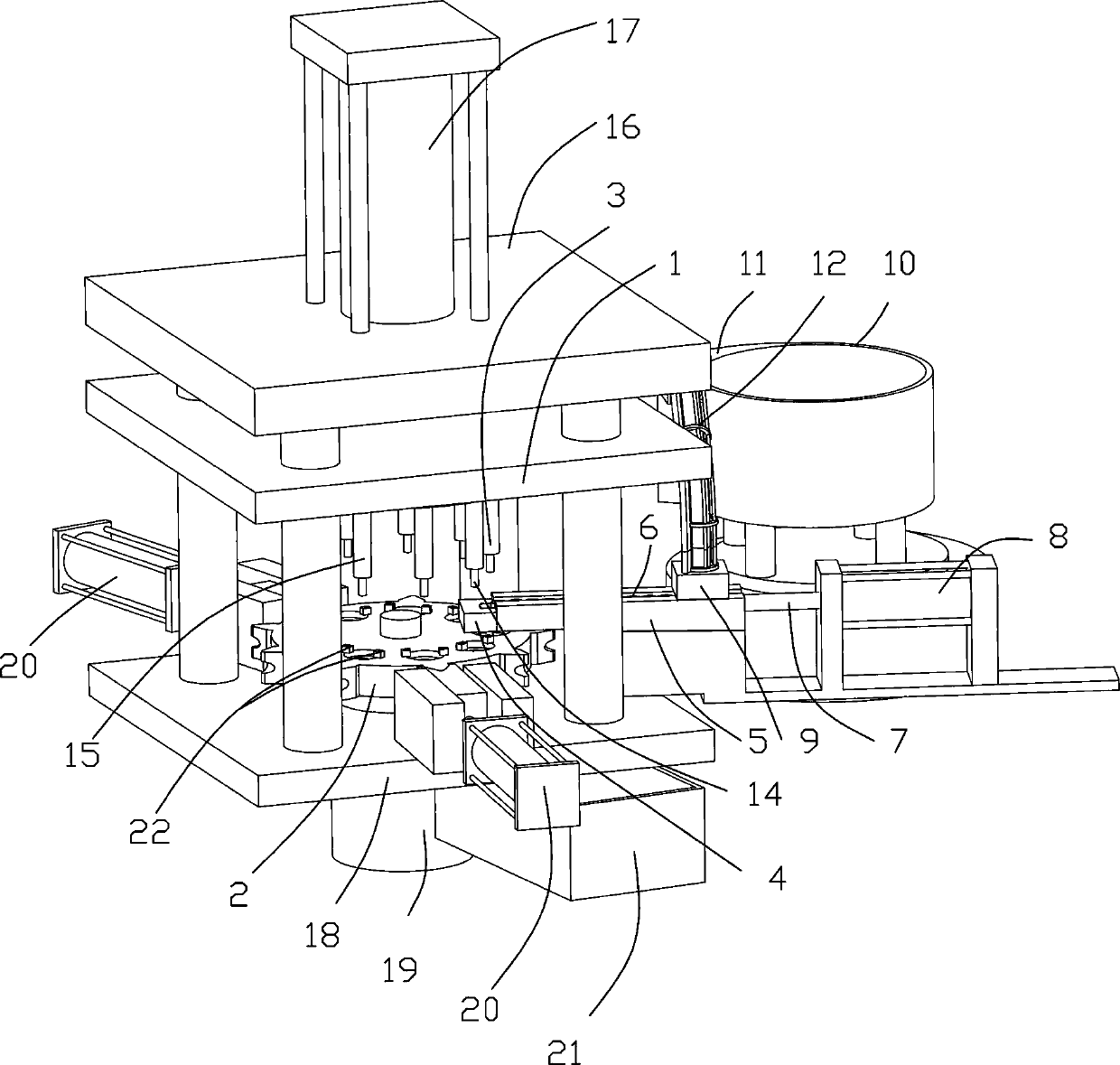
[0030] Such as figure 1 As shown, the punching machine includes a bracket 16, a vertical guide column on the bracket 16, an upper mold base 1 that can be raised and lowered in the vertical direction is provided on the guide pillar, and the bottom of the upper mold base 1 is provided with a punching station Corresponding to multiple stamping dies, there is an intermittent rotating turntable 2 directly below the stamping die. The turntable 2 is provided with positioning holes and positioning molds 1301 corresponding to the position of the stamping die. Below the turntable 2 is provided a fixed on the bracket 16 The fixing plate 18 is provided with a lower mold located below the positioning mold 1301 in the fixing plate 18, and the lower mold includes a sheath 1302 and a jack 1901 inserted in the sheath.

[0031] Preferably, the stamping die includes a plurality of stamping rods 15 corresponding to the stamping process, a feeding pressure rod 3 for feeding, and a discharge pressure ...

Embodiment 2

[0036] Preferably, an automatic feeding device is also provided on the side of the stamping die.

[0037] See figure 1 , The automatic feeding device includes a horizontal pushing mechanism, a blanking mechanism, and a vibration feeding mechanism.

[0038] The vibrating feeding mechanism includes a vibrating plate 10 on which is provided with a transfer platform 11 which is connected to the squirrel cage guide rail 12.

[0039] The horizontal pushing mechanism includes a horizontal guide rail 5 arranged below the exit of the squirrel cage guide rail 12. The horizontal guide rail 5 is provided with a through groove 6 for conveying and connecting pipes. One end of the through groove 6 is inserted with a push rod 7 driven intermittently by an air cylinder 8. The other end is connected with the positioning block 4 of the blanking mechanism.

[0040] See figure 1 with Figure 7 , The vertical positioning block 4 of the blanking mechanism is suspended between the upper mold base 1 and the...

Embodiment 3

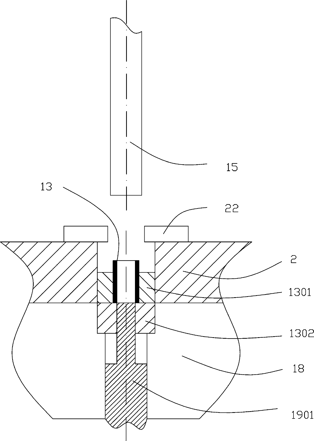
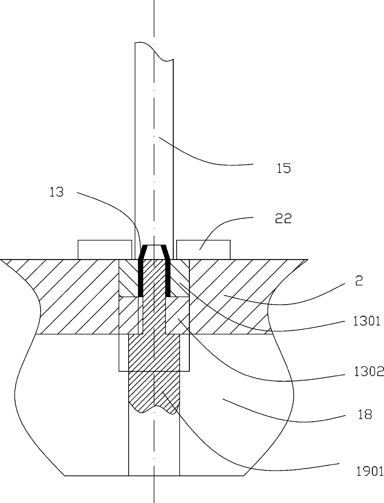
[0047] Such as Figure 2-Figure 4 As shown, combined with Example 1 and Example 2, the detailed description of the stamping process is as follows,

[0048] First, the upper die set 1 is driven by the upper pressure cylinder 17 to drive the punching rod 15, the discharge pressure rod 14 and the feeding pressure rod 3 are pressed down at the same time, and while the nozzle 13 in the turntable 2 is punched, a punching is completed simultaneously The discharge of the finished product and the feeding of 13 raw materials are taken over.

[0049] Secondly, the turntable rotates a station (each station corresponds to a positioning hole and a stamping die), and the unprocessed pipe is transferred to the first stamping station for stamping. Figure 2-Figure 4 As shown, the nozzle 13 is first in the positioning mold 1301. The sheath 1302 under the positioning mold 1301 axially blocks the nozzle 13 so that it cannot fall. The outer diameter of the front end of the ejector rod 1901 inside the ...


PUM


Abstract

The invention provides an air conditioner connecting pipe punching machine. The air conditioner connecting pipe punching machine comprises a support and a control device, wherein the support is vertically provided with guide columns, the guide columns are provided with an upper mold holder which can move up and down along the vertical direction, the bottom of the upper die frame is provided with a plurality of punching molds corresponding to punching workstations, an intermittent rotating plate is arranged right below the punching molds, the rotating plate is internally provided with positioning holes and positioning molds corresponding to the positions of the punching molds, a fixed plate which is fixed on the support is arranged below the rotating plate, a lower mold which is arranged below the positioning molds is arranged in the fixed plate, the lower mold comprises a jacket and an ejector rod which is inserted into the jacket, and the circumferential side of the rotating plate is also provided with a limiting mechanism and an automatic feeding device which are matched with the side wall of the rotating plate. The air conditioner connecting pipe punching machine is good in punching quality, high in automation degree and capable of realizing automatic feeding, eliminating the potential safety hazard of the manual operation and better guaranteeing the safety of workers.

Description

technical field [0001] The invention relates to a stamping machine, in particular to a stamping machine for an air-conditioning connection pipe, and belongs to the technical field of stamping machinery. Background technique [0002] The flanged pipe used for air conditioners is a common part of the air conditioner, and its dimensional accuracy and shape accuracy are required to be high. There are two common processing methods for the pipe. The precision of the method is the highest, but the processing efficiency is the lowest, and the manufacturing cost is very high. The other method is to punch it out through a precision stamping device. Restricted by the technical level, the stamping machines commonly used for pipe processing not only have the disadvantages of poor processing quality, high scrap rate, low degree of automation, and mostly semi-automatic operation, but also some of them need to be manually fed by workers during the operation process. Serious impact on work...

Claims


Application Information

Patent Timeline
Patent Type & Authority Applications(China)
IPC IPC(8): B21D43/06B21D22/08
Inventor 张春华
Owner ZHEJIANG PULISI AUTO PARTS
Why Eureka
Try Eureka