Cup holder assembly with adjustable cavity depth, corresponding vehicle sub-instrument frame and vehicle
A technology for cup holders and chambers, which is applied to vehicle parts, special positions of vehicles, transportation and packaging, etc. It can solve problems such as difficult operation, easy falling of sundries, and influence on the rotation of movable cup holders, so as to achieve convenient operation and guarantee The effect of long service life and simple structure
- Summary
- Abstract
- Description
- Claims
- Application Information
AI Technical Summary
Problems solved by technology
Method used
Image
Examples
Embodiment 1
[0048] Embodiment 1 A cup holder assembly with adjustable cavity depth
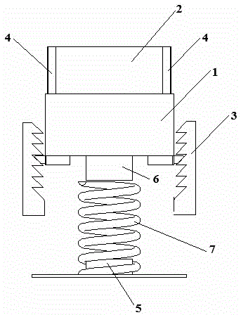
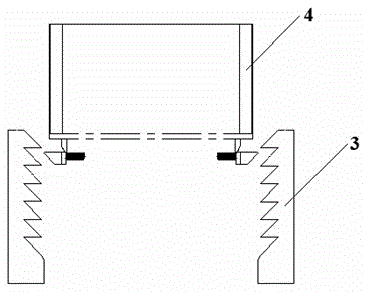
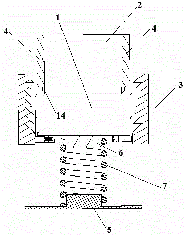
[0049] refer to figure 1 — Figure 4 , this embodiment includes a cylindrical groove fixedly arranged on the sub-dashboard frame of the vehicle body, an outer cup holder 1 with an open upper end and a lower end with a bottom, a cylindrical inner cup holder 2 with openings at both upper and lower ends, and a cylindrical inner cup holder 2 fixedly arranged on the inner wall of the groove And the locking slide rail 3 extending in the up and down direction.
[0050] Both the outer cup holder 1 and the inner cup holder 2 are cylindrical in shape.
[0051] The outer cup holder 1 and the inner cup holder 2 fit together. The outer cup holder 1 and the inner cup holder 2 are slidably fitted through the guide rails 4 extending in the vertical direction that are arranged on the outer wall of the inner cup holder 2 and the inner wall of the outer cup holder 1. The outer wall of the inner cup holder 2 or / and the in...
Embodiment 2
[0061] Embodiment 2 A cup holder assembly with adjustable cavity depth
[0062] This embodiment has all the structural features of Embodiment 1, and on this basis, a lateral locking elastic element 15 is provided.
[0063] refer to Figure 5 , the lateral locking elastic element 15 is located on the inner wall of the inner cup holder 2 at a distance of 1 / 3 from the upper cup mouth, and is an elastic plastic pad-like structure with an air outlet and a cavity, and is glued to the inner wall of the inner cup holder 2 fixed. The lateral locking elastic element 15 is arranged symmetrically at two (or three or four) places on the inner wall of the inner cup holder 2 in a circumferential direction. The radial rebound force will generate a lateral extrusion force on the water cup, thereby preventing the water cup from shaking left and right or back and forth.
[0064] This embodiment can realize the lateral locking of the container accommodated in the cup holder, so it has the buil...
Embodiment 3
[0066] Embodiment 3 A cup holder assembly with adjustable cavity depth
[0067] The only difference between this embodiment and Embodiment 2 is that the lateral locking elastic element is replaced by a sponge pad, and the functions of the two are the same.
[0068] The structure of other parts of this embodiment is exactly the same as that of Embodiment 2.
[0069] This embodiment can realize the lateral locking of the container accommodated in the cup holder, so it has the built-in requirement of being applicable to containers of different diameters under the premise of having a height-adjustable function. Of course, the grooves in this embodiment can also be replaced by grooves on other utensils. Correspondingly, the slide rail and the base are fixed in the grooves of the utensils for fixing containers such as water cups on corresponding utensils. The grooves in this embodiment can also be replaced by brackets on other utensils. Correspondingly, the slide rail and the base ...
PUM
 Abstract
Description
Claims
Application Information
 - R&D
- Intellectual Property
- Life Sciences
- Materials
- Tech Scout
- Unparalleled Data Quality
- Higher Quality Content
- 60% Fewer Hallucinations
Browse by: Latest US Patents, China's latest patents, Technical Efficacy Thesaurus, Application Domain, Technology Topic, Popular Technical Reports.
© 2025 PatSnap. All rights reserved.Legal|Privacy policy|Modern Slavery Act Transparency Statement|Sitemap|About US| Contact US: help@patsnap.com


