

Rotary moving member
A moving part, rotary technology, applied in auxiliary devices, auxiliary welding equipment, welding/cutting auxiliary equipment, etc., can solve problems such as increased workload, inconvenient operation, and difficulty in adapting to positioning efficiency.
Inactive Publication Date: 2010-02-10
杨清福
View PDF0 Cites 0 Cited by
- Summary
- Abstract
- Description
- Claims
- Application Information
AI Technical Summary
Problems solved by technology
[0002] In the existing positioning, use a tube with a hole that is the same as the root of the drill bit, insert the drill bit into the hole, weld one side of the two wings, then take out the inverted position, and re-draw it into the hole. Such a device is extremely inconvenient to operate. The increased workload, so it is difficult to adapt to the efficiency of positioning without changing the existing positioning welding
Method used
View moreImage
Smart ImageViewing Examples

Examples
Embodiment Construction
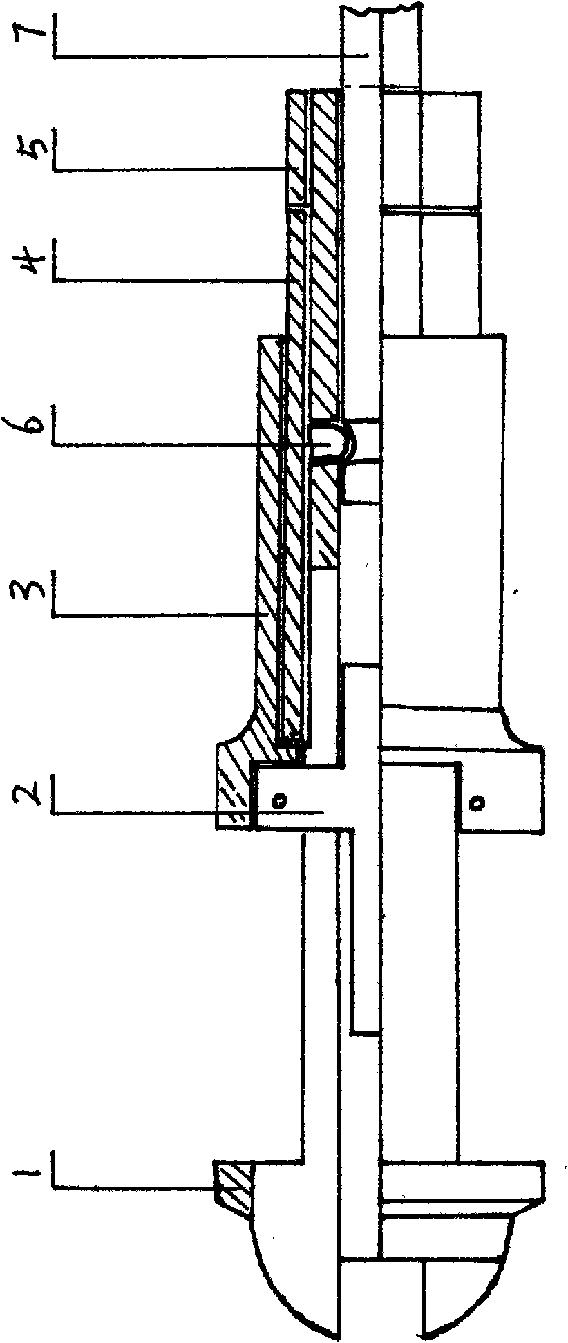
[0006] A rotary moving part, including the middle hole rotating head 1, the middle hole is equipped with a rod transmission piston 2 connected with a movable round handle 3, and the adjusting fixed sleeve 4 is connected with the rod of the middle hole rotating head 1, and there is a locking The cap 5 is connected with the lock buckle 6 and is rotatable at the center of the fixed connecting rod 7 at the same time.
[0007] Rotary head with middle hole 1, rod-passing piston 2 is installed in the middle hole, and a movable round handle 3 is connected to push it forward. When the weldment is finished welding, it is pushed by the transmission rod piston 2, and then protrudes from the center hole rotary head 1.
Login to View More PUM
 Abstract
The invention relates to a rotary moving member, which comprises a middle hole rotating head, wherein a driving rod piston is arranged in a middle hole. The rotary moving member is connected with a movable round handle; an adjusting fixed sleeve is arranged in the rotary moving member and is connected with a rod of the middle hole rotating head; and the rotary moving member is also connected witha locking cap and a lock catch, and simultaneously can rotate by taking a fixed connecting rod as a center. The rotary moving member is reasonably designed and skillfully constructed; and in order toquickly push out a weld assembly transferred by heat energy, the rotary moving member uses mechanical motions to transfer force so as to push the weld assembly away from the middle hole rotating head,thereby not only meeting the positioning requirement of a high-frequency welding structure assembly, but also greatly improving the working efficiency of the rotary moving member.
Description
technical field [0001] The invention relates to a rotary device for welding two-wing drill bits, in particular to a positioning unit used for integral welding of components and components, specifically a rotary moving part. Background technique [0002] In the existing positioning, use a tube with a hole that is the same as the root of the drill bit, insert the drill bit into the hole, weld one side of the two wings, then take out the inverted position, and re-draw it into the hole. Such a device is extremely inconvenient to operate. Therefore, it is difficult to adapt to the efficiency of positioning without changing the existing positioning welding. Contents of the invention [0003] In order to further improve the positioning work efficiency of the positioning part during welding, the present invention provides a rotary moving part. [0004] In order to achieve the above object, the present invention adopts the following scheme: a rotary moving part, including a rotati...
Claims
Login to View More Application Information
Patent Timeline
 IPC IPC(8): B23K37/04
Inventor杨清福
Owner杨清福