Rotation V-type T-structure bridge pier and construction thereof

A bridge pier and swivel technology, which is applied in the direction of basic structure engineering, bridges, bridge parts, etc., can solve the problems such as the difficulty of realizing the construction road and construction site of the portal pier scheme, the inability to guarantee the construction period, and the large impact on the operation of existing lines. Achieve the effect of reducing maintenance and repair work, saving demolition costs, and beautiful and stable structure

Active Publication Date: 2014-12-17
CHINA RAILWAY FIRST SURVEY & DESIGN INST GRP
View PDF5 Cites 4 Cited by
  • Summary
  • Abstract
  • Description
  • Claims
  • Application Information

AI Technical Summary

Problems solved by technology

[0003] The existing gate piers are constructed on both sides of the existing railway line, and the cover beams are constructed on top of them. The positions of the gate piers on both sides require construction roads and sites. The construction of the cover beams requires multiple skylights, which has a relatively large impact on the operation of the existing line. Big
Especially on both sides of the existing line in the urban area, there are often dense houses, narrow roads, and difficult demolition. It is difficult to realize the construction roads and construction sites on both sides required by the door-shaped pier scheme, or the cost of demolition is high, and the construction period cannot be guaranteed; at the same time, the existing line operating unit Strict requirements are often put forward for the construction of cover beams on the upper side, which not only requires strict protective measures, but also makes it difficult to coordinate the time of the skylight

Method used


Image

  • Rotation V-type T-structure bridge pier and construction thereof
  • Rotation V-type T-structure bridge pier and construction thereof
  • Rotation V-type T-structure bridge pier and construction thereof

Examples


Embodiment Construction

[0028] The present invention will be described in detail below in combination with specific embodiments.

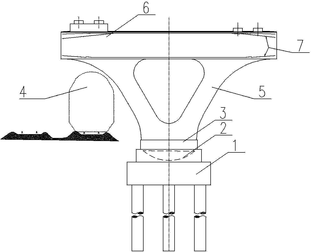
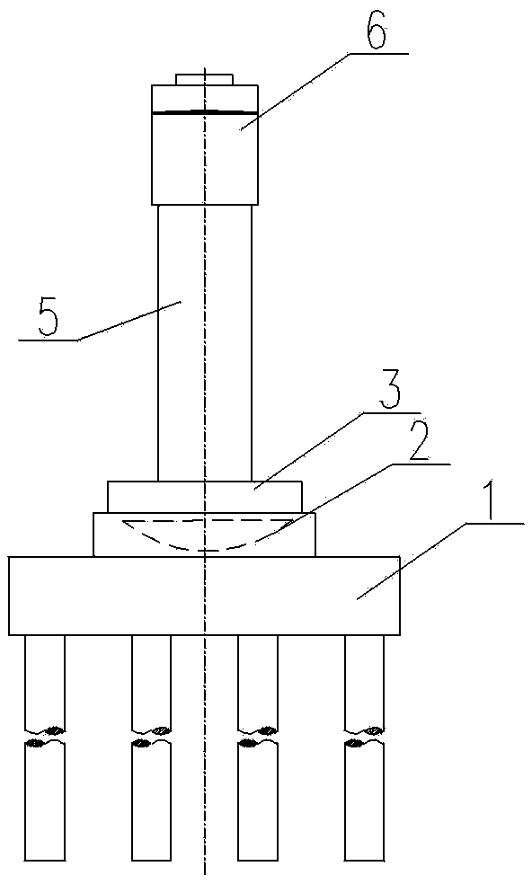
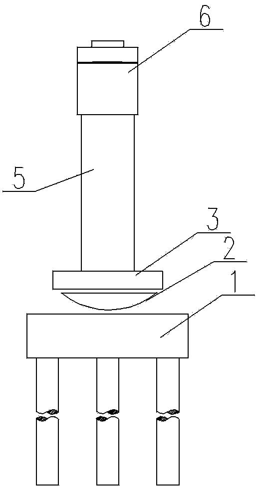
[0029] The invention relates to a swivel V-shaped T-structure bridge pier, which consists of a pile foundation, a cap, a pier arm 5 and a cover beam 6 from bottom to top. From bottom to top, the bearing platform is the lower turntable 1 and the upper turntable 3. The bottom of the upper turntable 3 is fixed with a rotating ball hinge 2. The rotating ball hinge 2 is placed in a spherically concave rotating groove set on the top surface of the lower turntable 1. The lower turntable 1 Concrete is poured on the outer side of the rotating spherical hinge 2 between the upper turntable 2 and forms a consolidation section. There are two pier arms 5, which are arranged in a "V" shape between the cap beam 6 and the cap, and the upper and lower ends of the pier arm 5 are connected with the cap beam 6 and the cap with arc chamfers. An inverted triangle gap is formed between the pier...


PUM


Abstract

The invention relates to a rotation V-type T-structure bridge pier and a construction thereof. When an included angle formed between a line and an existing busy trunk line through vertical crossing is smaller, cross-hole arrangement of a bridge is more difficult. The bridge pier is constructed on one side of the existing trunk line, and comprises a pile foundation, a supporting platform, pier arms and a cover beam from bottom to top, wherein the supporting platform is divided into a lower rotary table and an upper rotary table from bottom to top; a rotary spherical hinge is arranged between the upper rotary table and the lower rotary table; during line operation skylight time, the upper rotary table and the structure rotate to a designed position by taking the rotary spherical hinge as the center, concrete on the outer side of the rotary spherical hinge is poured to form a solid stage, and the lower rotary table and the upper rotary table are fixedly connected together to complete construction. Due to the adoption of a rotation V-type T-structure scheme, the construction only needs to be performed on one side of the existing line, requirements for roads and construction sites on the other side are reduced, the conditions that houses on two sides of the existing line in an urban area are dense and are difficult to remove are facilitated, the removal cost is greatly reduced, and the construction period is guaranteed; meanwhile, due to the adoption of rotation construction, the influence on operation of the existing line is minimized.

Description

technical field [0001] The invention belongs to the technical field of railway bridge engineering, and in particular relates to a swivel V-shaped T-structure bridge pier and a construction method thereof. Background technique [0002] In recent years, my country's transportation infrastructure construction has developed rapidly, especially the development of high-speed railways represented by passenger dedicated lines and expressways in highway engineering. When the angle between the two is small, the layout of the span of the bridge is more difficult. There are two general solutions: one is to lay out a large span, and one span spans the existing railway; the other is to adopt the traditional gate type pier scheme. However, the former will increase the elevation of the newly built line, and will greatly increase the project investment due to the huge amount of structural objects. This scheme will become unrealizable when the angle between the two lines is particularly small...

Claims


Application Information

Patent Timeline
Patent Type & Authority Applications(China)
IPC IPC(8): E01D19/02E02D27/14
Inventor 刘彦明陈频志文强
Owner CHINA RAILWAY FIRST SURVEY & DESIGN INST GRP
Why Eureka
Try Eureka