H section steel girder-column minor axis connecting top and bottom angle steel node and preparing method of H section steel girder-column minor axis connecting top and bottom angle steel node

A technology of H-shaped steel and angle steel, which is applied in the direction of construction, building structure, and building material processing, can solve the problems of analysis, design, and installation difficulties, and the limited number of nodes, so as to delay local buckling and bulging, and improve overall rigidity And the effect of high bearing capacity and high compressive strength

Active Publication Date: 2014-12-17
INNER MONGOLIA UNIV OF SCI & TECH
View PDF11 Cites 7 Cited by
  • Summary
  • Abstract
  • Description
  • Claims
  • Application Information

AI Technical Summary

Problems solved by technology

However, due to the difficulties in analysis, design and installation of H-shaped steel beam-column weak-axis connections, there are few studies on H-shaped steel beam-column weak-axis joints, and the number of joints that can be put into practical use is even more limited.

Method used


Image

  • H section steel girder-column minor axis connecting top and bottom angle steel node and preparing method of H section steel girder-column minor axis connecting top and bottom angle steel node
  • H section steel girder-column minor axis connecting top and bottom angle steel node and preparing method of H section steel girder-column minor axis connecting top and bottom angle steel node
  • H section steel girder-column minor axis connecting top and bottom angle steel node and preparing method of H section steel girder-column minor axis connecting top and bottom angle steel node

Examples


Embodiment Construction

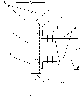
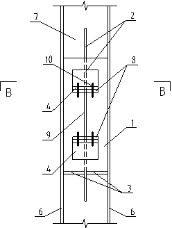
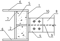
[0027] In the present invention, the H-shaped steel column is composed of a web 7 and two flanges 6 arranged at both ends of the web 7 , and the H-shaped steel beam is composed of a web 8 and two flanges 9 arranged at both ends of the web 8 . Between the two flanges 6 of the H-shaped steel column, a gusset plate 1 is welded at a position flush with the outer edge of the flange 6 . A stiffening plate 2 is welded at the vertical center line inside the gusset plate 1, and the gusset plate and the stiffening plate are perpendicular to each other. The stiffener 2 is trapezoidal, wherein the short bottom of the trapezoid is welded to the gusset plate 1 , and the long bottom is welded to the web 7 of the H-shaped steel column. The angle steel 4 is composed of two top angle steels and bottom angle steels with the same structure, the top angle steel is located at the top, and the bottom angle steel is located below. One limb of the angle steel 4 is provided with double rows of high-str...


PUM


Abstract

The invention discloses an H section steel girder-column minor axis connecting top and bottom angle steel node and a preparing method of the H section steel girder-column minor axis connecting top and bottom angle steel node, wherein the H section steel girder-column minor axis connecting top and bottom angle steel node is characterized in that a T-shaped combined body is welded on an H section steel column, angle steel is symmetrically arranged on the T-shaped combined body, the angle steel is fixedly connected with the H section steel column, a supporting plate is welded at the bottom of the T-shaped combined body, and two spaces defined by the H section steel column, the T-shaped combined body and the supporting plate are filled with concrete fillers. The preparing method comprises the following steps that a node plate and a stiffening plate are welded into the T-shaped combined body; two sections of angle steel are welded at the outer side of the node plate; the T-shaped combined body and the supporting plate are welded on the H section steel column; the angle steel and the H section steel column are connected by high-strength bolts; a rectangular region of a node area is poured with concrete. The H section steel girder-column minor axis connecting top and bottom angle steel node and the preparing method have the advantages that the respective advantages of steel and concrete are fully utilized, the anti-seismic performance is good, the bearing capability is great, and the construction is simple and convenient.

Description

technical field [0001] The invention relates to an H-shaped steel beam-column weak shaft connection top-bottom angle steel joint and a preparation method thereof, belonging to the field of building structure engineering. Background technique [0002] Steel frame is a safe, reliable, lightweight, high-strength, and fast-construction structural system, which has been widely used in architectural structural engineering. In earthquake disasters, due to unreasonable design and construction, frame joints are often prone to failure prior to structural members, resulting in structural seismic performance that cannot meet the requirements of seismic design. In general, the steel frame system is a frame in both vertical and horizontal directions, that is, both the strong axis and the weak axis of the H-shaped steel column are connected to the H-shaped steel beam. However, due to the difficulties in analysis, design and installation of H-shaped steel beam-column weak-axis connections,...

Claims


Application Information

Patent Timeline
Patent Type & Authority Applications(China)
IPC IPC(8): E04B1/58E04G21/00
Inventor 赵根田高潮王珊周慧茹朱宇
Owner INNER MONGOLIA UNIV OF SCI & TECH
Why Eureka
Try Eureka