An Improved Bearing Annular Snap-Lock Cage Structure

A cage and spring lock technology, applied in the direction of bearing components, shafts and bearings, mechanical equipment, etc., can solve the problems of difficult beam width, low production efficiency, and difficult control of the size of the lock 3, and reduce the radial cutting force , easy-to-control effects

Active Publication Date: 2016-08-17
LUOYANG VSG BEARING
View PDF7 Cites 0 Cited by
  • Summary
  • Abstract
  • Description
  • Claims
  • Application Information

AI Technical Summary

Problems solved by technology

When machining the cage, the guide bevel 7 is milled out on a CNC drilling and milling machine, and the production efficiency is low
Because the spring lock beam 5 plays an elastic role, its beam is not easy to be wide, so when milling the guide slope 7 on the side of the spring lock beam 5, under the action of a large radial cutting force on the drilling and milling machine, an elastic let-off of the knife will occur, resulting in The size of the lock port 3 is not easy to control

Method used


Image

  • An Improved Bearing Annular Snap-Lock Cage Structure
  • An Improved Bearing Annular Snap-Lock Cage Structure
  • An Improved Bearing Annular Snap-Lock Cage Structure

Examples


Embodiment Construction

[0031] In order to further explain the technical means and effects of the present invention to achieve the intended purpose of the invention, the following is a specific implementation of an improved bearing annular snap-lock cage structure proposed according to the present invention in conjunction with the accompanying drawings and preferred embodiments. Ways, methods, steps, features and effects thereof are described in detail below.

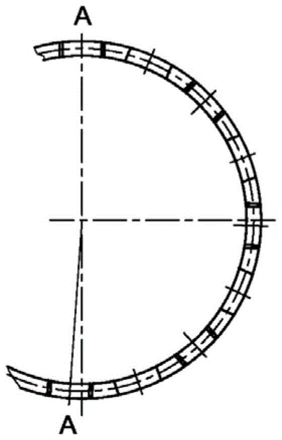
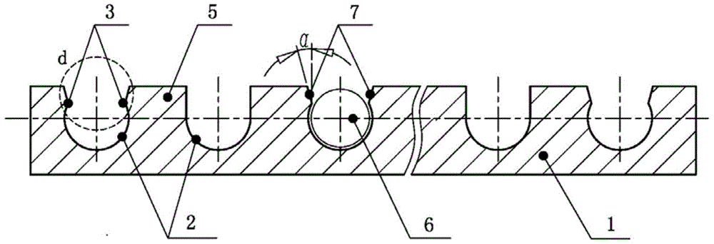
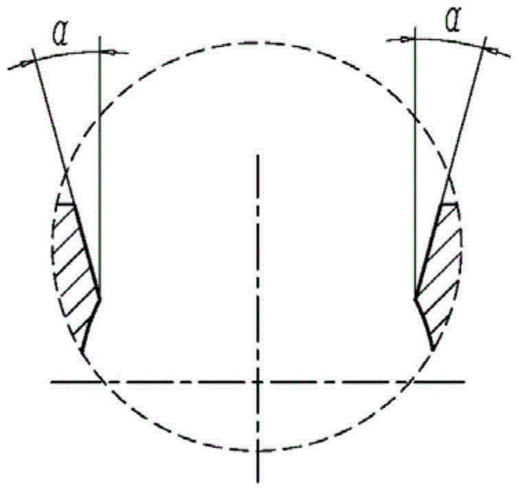
[0032] see Figure 2A , Figure 2B , Figure 2C and Figure 3A , Figure 3B , Figure 3C As shown, an improved bearing annular snap lock cage structure of the present invention includes: cage 1, pocket hole 2, lock opening 3, guiding curved surface 4, snap lock beam 5 and rolling body 6, wherein cage 1 is An integrally formed ring-shaped cylindrical structure frame, the cage 1 is provided with pocket holes 2 on the circumference, and a snap lock beam 5 is provided between the openings of every two pocket holes 2, and a circle is provided ...


PUM


Abstract

The present invention relates to an improved ring-shaped snap-lock cage structure for bearings, including: a cage, a pocket, a lock, a guiding curved surface, a snap-lock beam, and a rolling body, wherein the cage is an integrally formed annular cylindrical Structural frame, the circumference of the cage is provided with pocket holes, and a spring lock beam is provided between every two pocket hole openings, and an arc-shaped guide surface is provided at the joint between the spring lock beam and the pocket hole opening, and the pocket hole and the guide surface There is a lock opening with a lock rolling body between them, and the rolling body is placed in the pocket hole. In the present invention, the guiding slope is changed into a guiding curved surface, which is convenient for processing, easy to control the size of the locking port, and improves the production efficiency.

Description

technical field [0001] The invention relates to a bearing, in particular to an improved structure of an annular snap-lock cage for the bearing. Background technique [0002] The structure of bearing annular snap-lock cage is a common bearing cage structure at this stage, please refer to Figure 1A , Figure 1B and Figure 1C As shown, they are respectively the schematic diagram of the ring-shaped snap lock cage structure of the bearing in the prior art, the expanded partial structure section view and the partial enlarged view. °) slope. When machining the cage, the guide bevel 7 is milled out on a CNC drilling and milling machine, and the production efficiency is low. Because the spring lock beam 5 plays an elastic role, its beam is not easy to be wide, so when milling the guide slope 7 on the side of the spring lock beam 5, under the action of a large radial cutting force on the drilling and milling machine, an elastic let-off of the knife will occur, resulting in Lock ...

Claims


Application Information

Patent Timeline
Patent Type & Authority Patents(China)
IPC IPC(8): F16C33/38F16C33/46
Inventor 邹小洛刘成斌张翠英
Owner LUOYANG VSG BEARING
Why Eureka
Try Eureka