Method and device for preventing high-pressure and low-pressure flare gas channeling of gas inlet cabinet

A flare gas and low-pressure technology, which is applied in gas/liquid distribution and storage, pipeline systems, mechanical equipment, etc., can solve problems such as safety hazards, flare gas cross-channeling, and out-of-synchronization of venting, so as to improve safety and reliability and simplify the process , The effect of simple equipment structure

Inactive Publication Date: 2014-12-17
SINOPEC LUOYANG PETROCHEM ENG CORP +1
View PDF5 Cites 4 Cited by
  • Summary
  • Abstract
  • Description
  • Claims
  • Application Information

AI Technical Summary

Problems solved by technology

[0003] Due to the asynchronous venting and pressure fluctuations in the high-pressure and low-pressure flare venting systems, when the main valve of the intake cabinet is closed, the phenomenon of high-pressure and low-pressure flare gas crossing will occur, causing a great safety hazard. In order to avoid this phenomenon In the petrochemical industry, the pressure interlock device is often used to control the high and low pressure intake valves. However, due to the instability of the pressure signal source, the time delay of the switching valve and the response speed of the control system, this method cannot Fundamentally solve the occurrence of high and low pressure flare gas channeling, prevent the occurrence of high and low pressure flare gas channeling, and put petrochemical equipment at risk

Method used


Image

  • Method and device for preventing high-pressure and low-pressure flare gas channeling of gas inlet cabinet

Examples


Embodiment 1

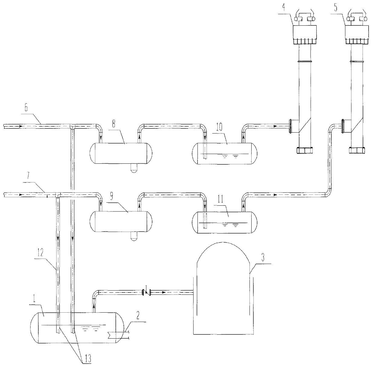
[0020] Such as figure 1 As shown, when the high and low pressure flare gas is recovered normally, as long as the high and low pressure flare gas can break through the water seal of the water seal tank, it can enter the gas cabinet, and the gas entering the gas cabinet is used as fuel for backup;

Embodiment 2

[0022] Such as figure 1 As shown, when the main valve of the air inlet cabinet is closed, when the high-pressure flare gas enters the water-sealed tank, the pressure in the water-sealed tank rises, and the water in the water-sealed tank is pressed into the low-pressure flare gas intake riser. When the gas pressure in the standpipe plus the height of the water-filled liquid column is equal to the pressure of the high-pressure flare gas in the water-sealed tank, it can be ensured that the high-pressure flare gas will not escape into the low-pressure flare gas pipeline to prevent the danger caused by the blow-by gas.

Embodiment 3

[0024] Such as figure 1 As shown, when the high and low pressure flare gas is recovered normally, as long as the high and low pressure flare gas can break through the water seal of the water seal tank by 100mm, it can enter the gas cabinet, and the gas entering the gas cabinet can be used as fuel for backup.

[0025] When the main valve of the air inlet cabinet is closed, the high-pressure flare gas enters the water-sealed tank, the pressure in the water-sealed tank rises, and the water in the water-sealed tank is pressed into the low-pressure flare gas pipeline standpipe. The diameter of the water-sealed tank is 3000mm, and the high-pressure, The insertion depth of the low-pressure flare gas pipeline is 100mm. When the gas pressure in the low-pressure flare gas pipeline is 0.004MPaG plus the height of the water-filled liquid column is 6300mm, which is equal to the pressure of the high-pressure flare gas in the water-sealed tank is 0.067MPaG, the high-pressure flare gas can be ...


PUM


Abstract

The invention discloses a method and device for preventing high-pressure and low-pressure flare gas channeling of a gas inlet cabinet. The method comprises the steps that high-pressure flare gas enters the gas inlet cabinet through a high-pressure flare gas pipeline and a water sealing tank, and low-pressure flare gas enters the gas inlet cabinet through a low-pressure flare gas pipeline and a water sealing tank. The method and device avoid the gas channeling danger, the method is simple in process, adopted equipment is simple in structure, and safety and reliability are achieved.

Description

technical field [0001] The invention belongs to the field of discharge and recovery of combustible gas in oil refining and chemical enterprises, and relates to a method for preventing mutual channeling when gas cabinets collect high-pressure and low-pressure discharge air in oil refining and chemical enterprises. Background technique [0002] The combustible gas discharge and recovery system in oil refining and chemical enterprises is an important measure to ensure safe production and an environmental protection and energy-saving measure. Due to the difference in the back pressure of the combustible gas discharged from the device, two discharge systems are usually set up, namely high and low pressure. There are two systems for flare venting. During normal production, high-pressure and low-pressure flare gas enters the gas cabinet facility for recovery as much as possible, and then is compressed and sent to the dry gas desulfurization device for desulfurization and used as pla...

Claims


Application Information

Patent Timeline
Patent Type & Authority Applications(China)
IPC IPC(8): F17D5/00
Inventor 程继元何龙辉徐兴文刘立新谢伟峰闫璐
Owner SINOPEC LUOYANG PETROCHEM ENG CORP
Why Eureka
Try Eureka