
Method for determining sensitivity of each sensor in mechanical equipment vibrating sensor network

A technology of vibration sensors and mechanical equipment, applied in instruments, measuring devices, measuring ultrasonic/sonic/infrasonic waves, etc., can solve problems that cannot be used to determine the importance or sensitivity of sensor nodes, and are not suitable for research purposes

Inactive Publication Date: 2014-12-17
AIR FORCE UNIV PLA
View PDF4 Cites 12 Cited by
  • Summary
  • Abstract
  • Description
  • Claims
  • Application Information

AI Technical Summary

Problems solved by technology

However, the above methods are too subjective, or are only applicable to the field of target recognition based on multi-sensors, and are not suitable for the research purpose of the present invention, that is, they cannot be used to determine the importance or sensitivity of each sensor node in the mechanical equipment sensor network. degree size

Method used


Image

  • Method for determining sensitivity of each sensor in mechanical equipment vibrating sensor network
  • Method for determining sensitivity of each sensor in mechanical equipment vibrating sensor network
  • Method for determining sensitivity of each sensor in mechanical equipment vibrating sensor network

Examples


specific Embodiment

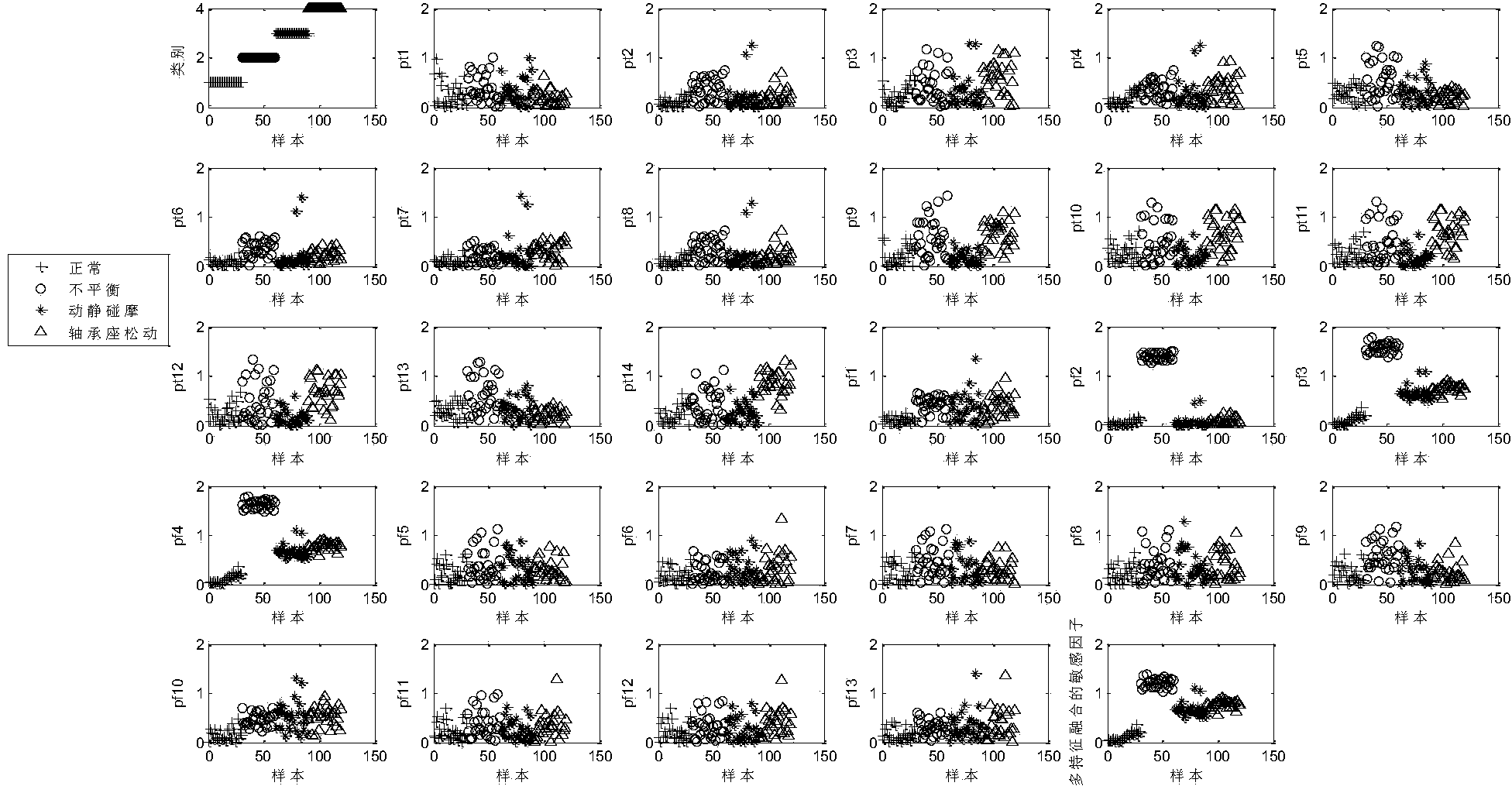
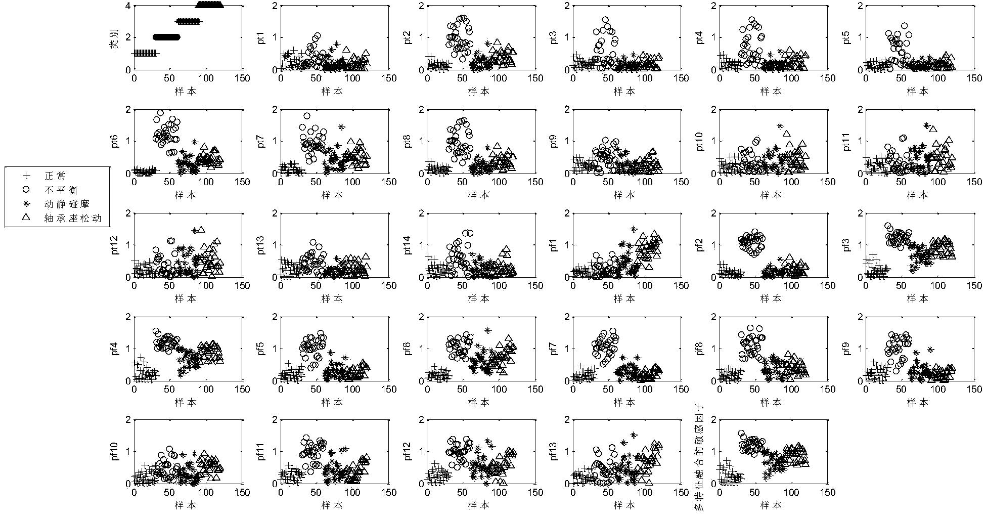
[0104] The effect of the method for evaluating the sensitivity of each node of the mechanical vibration sensor network proposed by the present invention is tested and verified with the fault simulation experiment data of the aeroengine rotor.

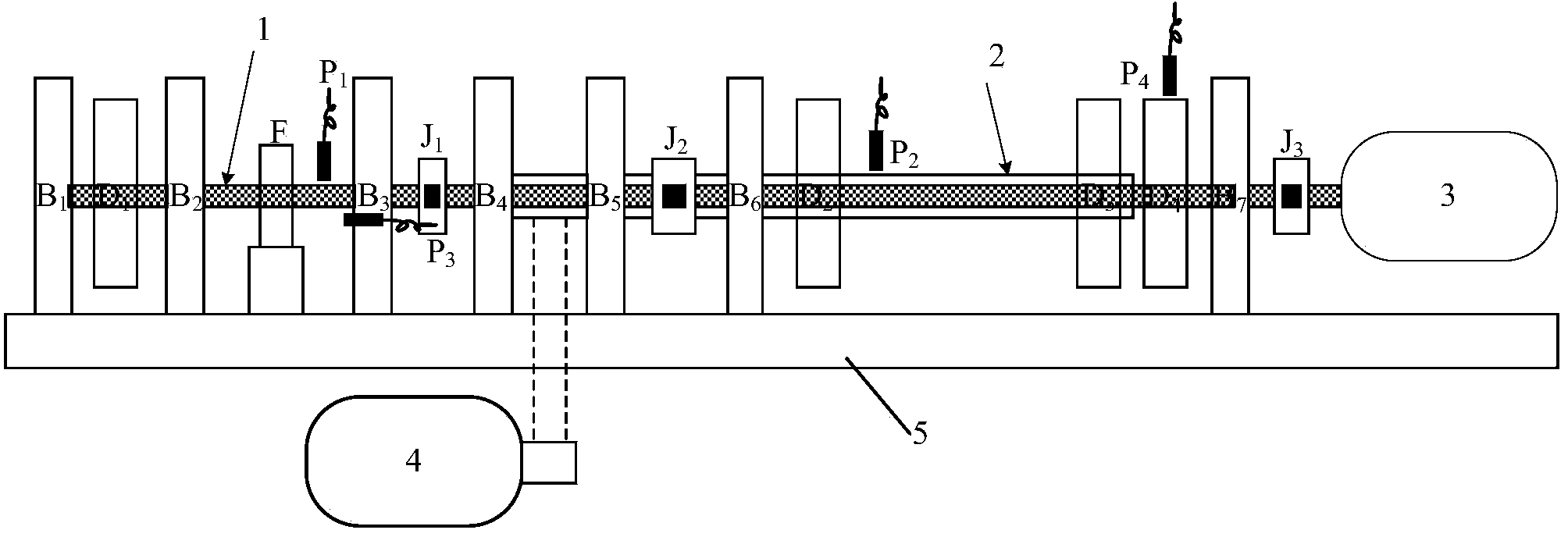
[0105] The rotor fault simulation experiment uses the figure 1 The basic components of the double-span rotor test bench shown include: base, two motors, two bearings, couplings, discs, etc. Among them, B i (i=1,...,7) is the bearing seat, D i ((i=1,…,4) is the rotor disk, P 1 ,P 2 , P 3 is the vibration sensor, P 4 is the speed sensor, J 1 、J 2 、J 3 for the coupling.

[0106] The shafts are connected by a flexible coupling, and the motor and the shaft are also connected by a flexible coupling. In order to improve the installation accuracy of the rotor, so that the rotor can run at high speed, and also to solve the lubrication problem of the high-speed rotor, the bearings are all low-friction deep groove ball bearings with self...


PUM


Abstract

The invention relates to a method for determining the sensitivity of each sensor in a mechanical equipment vibrating sensor network. A vibrating sensor network node sensitivity evaluation index is provided according to the actual conditions of the vibrating sensor network and by using common complex network importance evaluation indexes and methods as reference. The vibrating sensor network node sensitivity evaluation index is a sensor network sensitivity factor based on multi-feature fusion. The vibrating sensor network sensitivity factor must sensitively and accurately reflect system state change and measure the sensitivity of all sensors to the same state. The calculation thought of the vibrating sensor network sensitivity factor is characterized in that maximization of the distance between an abnormal fault state and a normal state can be achieved by using the normal state as reference; the factor is comparable, and the sensitivity of each sensor to the same fault or abnormal state can be measured. Compared with a single feature, the method has the advantages that the method considers more feature attributes, system state change can be comprehensively and accurately reflected, and the sensitivity of all the sensors to the same state can be well measured. In addition, by the method, the importance of the nodes of the sensor network can be evaluated and sorted, the key nodes can be found, and foundation is laid for sensor network consistency decision fusion.

Description

technical field [0001] The invention belongs to the field of fault diagnosis of mechanical equipment, and relates to a method for determining the sensitivity of each sensor in a vibration sensor network of mechanical equipment. Background technique [0002] The main purpose of the vibration sensor network of mechanical equipment is to reflect the state changes of the equipment through multi-sensor vibration monitoring, and to detect whether there is an abnormality or failure. Generally speaking, for different faults or abnormal states, the sensitivities of position sensors of different nodes in the network are different, that is, for the same fault or abnormal state, the sensitivities of sensors of different nodes in the network are different. The sensor network sensitivity factor refers to the index that can determine the degree of deviation of the measurement data of each sensor in the network from the normal state, that is, determine the sensitivity of each sensor to the ...

Claims


Application Information

Patent Timeline
Patent Type & Authority Applications(China)
IPC IPC(8): G01H17/00
Inventor 胡金海
Owner AIR FORCE UNIV PLA
Learn More