
Method and circuit for controlling fly-back switching power supplies of zero-voltage switches

A technology of zero-voltage switching and switching power supply, applied in control/regulation systems, high-efficiency power electronic conversion, electrical components, etc., can solve problems such as fluctuations, reduce turn-on losses, reduce the risk of auxiliary power supply overvoltage protection, and suppress voltage Elevated effect

Active Publication Date: 2014-12-17
MORNSUN GUANGZHOU SCI & TECH
View PDF6 Cites 29 Cited by
  • Summary
  • Abstract
  • Description
  • Claims
  • Application Information

AI Technical Summary

Problems solved by technology

[0013] The object of the present invention is to provide a control method for flyback switching power supply that realizes zero-voltage turn-on, so as to realize zero-voltage turn-on of the main power switch tube in the full input voltage range, improve circuit transmission efficiency, and solve the problem of auxiliary power supply due to cross regulation. large-scale fluctuation problem caused by
[0014] Correspondingly, another object of the present invention is to provide a flyback switching power supply control circuit that realizes zero-voltage turn-on, so as to realize zero-voltage turn-on of the main power switch within the full input voltage range and improve circuit transmission efficiency. Solve the problem of wide fluctuations in auxiliary power due to cross regulation

Method used


Image

  • Method and circuit for controlling fly-back switching power supplies of zero-voltage switches
  • Method and circuit for controlling fly-back switching power supplies of zero-voltage switches
  • Method and circuit for controlling fly-back switching power supplies of zero-voltage switches

Examples


Embodiment Construction

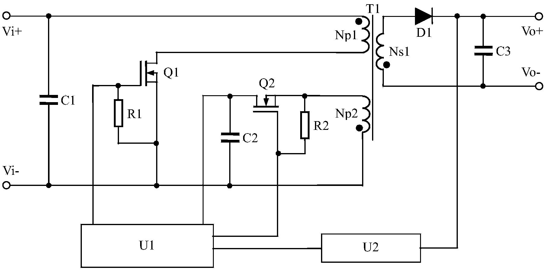
[0035] see figure 1 , is the flyback switching power supply control circuit of the zero voltage switch of the present invention, which includes: a flyback switching power supply circuit and an auxiliary power supply circuit,

[0036] Among them, the flyback switching power supply circuit includes a resistor R1, a first switching tube Q1, a transformer T1 with a primary winding Np1 and a secondary winding Ns1, a diode D1, and a capacitor C3. The drain of the first switching tube Q1 is connected to the primary side The opposite end of the winding Np1 is connected, the end of the same name of the primary winding Np1 is connected to the input positive terminal Vi+, the source of the first switching tube Q1 is connected to the input negative terminal Vi-, the gate of the first switching tube Q1 is connected to the control system The driving signal DRV1 terminal is connected, the first switching tube Q1 source and the grid are connected in parallel with the resistor R1; the opposite...


PUM


Abstract

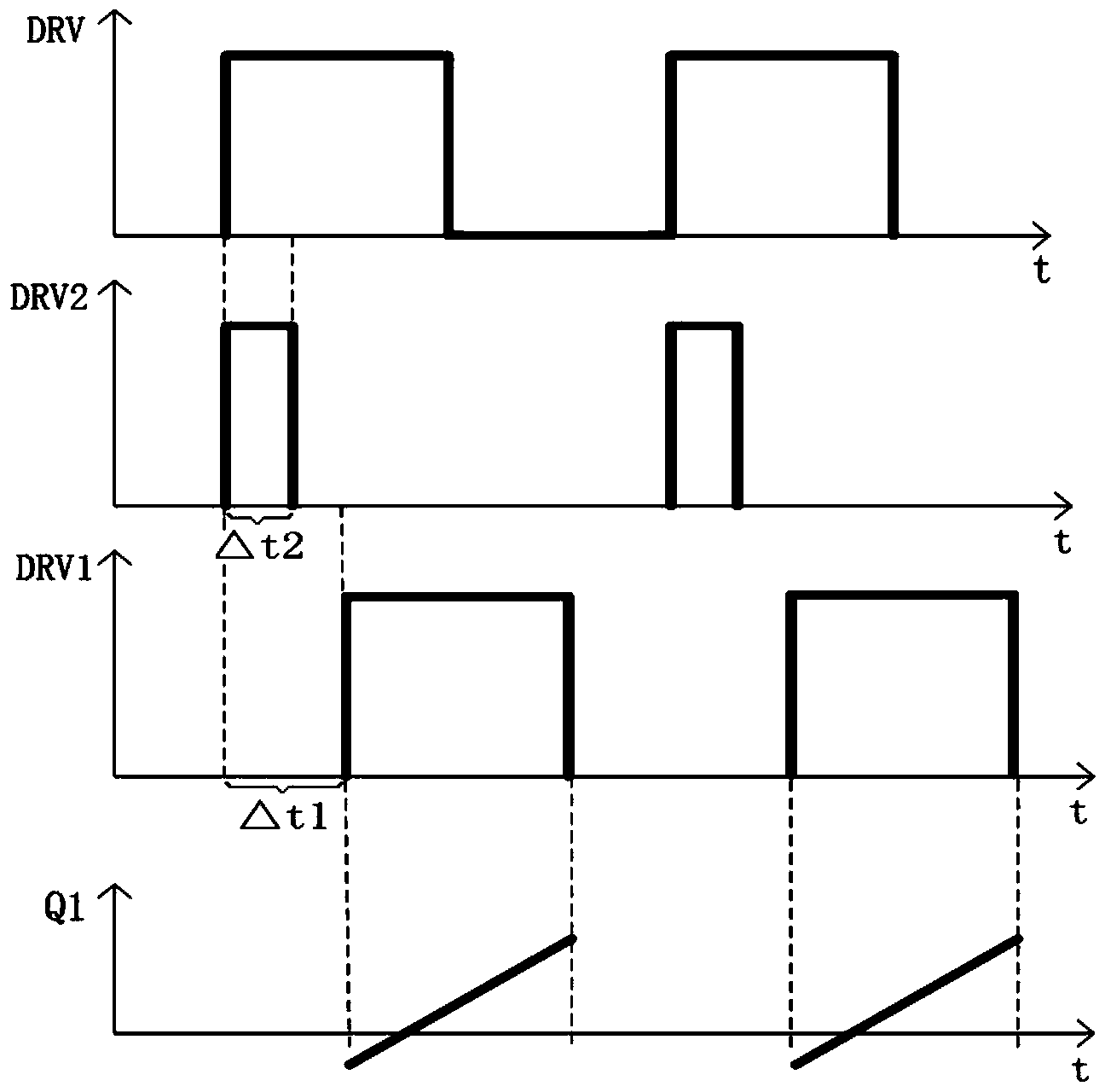
The invention discloses a scheme for controlling fly-back switching power supplies of zero-voltage switches. The scheme for controlling the fly-back switching power supplies has the advantages that the traditional rectifying tubes of auxiliary power supplies are replaced by controllable auxiliary power switching tubes by the design, the auxiliary power switching tubes are turned on for a period of time before a main power switching tube is turned on, accordingly, a primary winding of a transformer is reversely excited to generate negative currents, parasite diodes of the main power switching tube are turned on, the main power switching tube can be turned on at zero voltage, turn-on loss of the main power switching tube can be reduced, redundant energy of the auxiliary power supplies can be fed to input ends, and the efficiency of a circuit can be improved.

Description

technical field [0001] The invention relates to the field of a flyback switching power supply, in particular to a control method and circuit of a flyback switching power supply with a zero-voltage switch. Background technique [0002] With the development of technology, high frequency has become a trend in the development of switching power supplies. High frequency can effectively reduce the volume of switching power supplies, but high frequency also leads to increased switching tube losses of switching devices, so in high frequency How to achieve zero-voltage, zero-current turn-on and turn-off of switching devices at the same time has become the focus of high-frequency research. [0003] The flyback circuit topology with simple circuit structure, low cost and excellent performance is widely used in small and medium power switching power supplies. The flyback switching power supply has two operating modes: continuous mode and discontinuous mode. Generally, the continuous mod...

Claims


Application Information

Patent Timeline
IPC IPC(8): H02M3/28H02M3/335
CPCY02B70/10
Inventor 开秋月周耀彬金结冰袁源郭启利
Owner MORNSUN GUANGZHOU SCI & TECH
Learn More