Multi-frequency crystal oscillator circuit
A technology of crystal oscillation and oscillation circuit, applied in the direction of power oscillators, electrical components, etc., can solve the problems of large crystal oscillator circuit area, low reusability, and large power consumption, so as to reduce power consumption, realize reusability, Effect of reducing area and cost
- Summary
- Abstract
- Description
- Claims
- Application Information
AI Technical Summary
Problems solved by technology
Method used
Image
Examples
Embodiment Construction
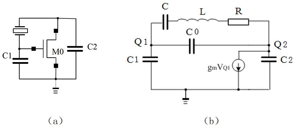
[0030] figure 1 a shows the structure diagram of the Pierce oscillation circuit, in which the MOS transistor M0 is used as the amplification unit, figure 1 b is its AC equivalent circuit diagram. The multi-frequency crystal oscillating circuit adopts a Pierce oscillating circuit structure. According to the Barkhausen criterion, the conditions for circuit oscillation should be satisfied:
[0031] Z C +Z M =0 (1)
[0032] Further solving can obtain the critical transconductance:
[0033] G m =(C 1 +C2) 2 *(ωC T ) 2 / C 1 C 2 (2)
[0034] Among them, "*" represents the multiplication sign, C T =C 0 +C 1 C 2 / (C 1 +C 2 ), because the circuit needs to meet the requirements of extremely low power consumption, the device is required to work in the subthreshold region. At this time, the drain current has the following relationship with the voltage of each terminal:
[0035] I d =sI s0 e vg / nVT (e -VS / VT -e -VD / VT ) (3)
[0036] where V G , V D and V S is t...
PUM
 Abstract
Description
Claims
Application Information
 - R&D
- Intellectual Property
- Life Sciences
- Materials
- Tech Scout
- Unparalleled Data Quality
- Higher Quality Content
- 60% Fewer Hallucinations
Browse by: Latest US Patents, China's latest patents, Technical Efficacy Thesaurus, Application Domain, Technology Topic, Popular Technical Reports.
© 2025 PatSnap. All rights reserved.Legal|Privacy policy|Modern Slavery Act Transparency Statement|Sitemap|About US| Contact US: help@patsnap.com


