System for storage and transportation of spent fuel

A tank storage and storage tank technology, which is applied in the direction of portable protective containers, greenhouse gas reduction, climate sustainability, etc., to improve internal heat transfer and heat dissipation

Active Publication Date: 2014-12-17
TN AMERICAS LLC
View PDF13 Cites 14 Cited by
  • Summary
  • Abstract
  • Description
  • Claims
  • Application Information

AI Technical Summary

Problems solved by technology

However, the syste

Method used


Image

  • System for storage and transportation of spent fuel
  • System for storage and transportation of spent fuel
  • System for storage and transportation of spent fuel

Examples


Embodiment Construction

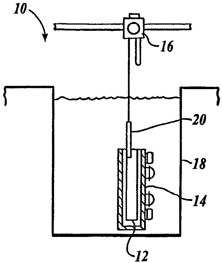
[0048] A horizontal modular dry irradiated fuel (spent fuel) storage system will first be described. Referring to Figures 1-4, a horizontal modular dry irradiated fuel storage system 10 is depicted in accordance with an embodiment of the present invention. Additionally, a process for storing irradiated fuel is described. As stated in more detail below, the systems and processes described herein are improvements over previous systems and processes (as seen in FIGS. 1-4 ) described in U.S. Patent No. 4,780,269, the disclosure of which The contents are expressly incorporated herein by reference.

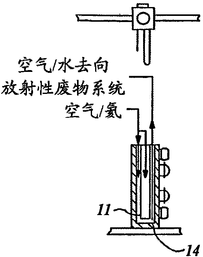
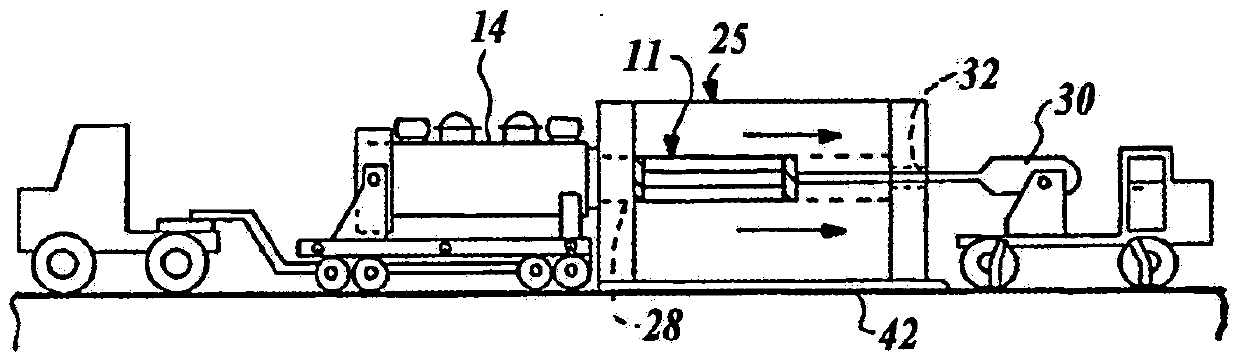
[0049] Referring to Figure 1, system 10 utilizes a specially designed dry shielding tank assembly 12, which in Figure 5-10 shown in more detail in , as described in more detail below. Canister assembly 11 is inserted into transfer bucket 14 . The transfer bucket 14 and canister assembly 11 may be lowered by crane into a water-filled irradiated fuel storage pool 18 (see Figures 1 an...


PUM


Abstract

A concrete storage module (26) is adapted to slideably receive a cylindrical canister assembly (12) therein. Heat dissipation fins (62) and a tubular heat shield (96) are disposed within the module to help dissipate heat emitted from nuclear fuel assemblies stored in the canister to air flowing through the module. The canister assembly (12) is composed of a basket assembly (70) constructed from multi-layer structural plates disposed in cross-cross or egg carton configuration. A single port tool (106) is provided for draining water from the canister (12) and replacing the drain water with make-up gas. The single port tool is mounted in the cover (100) of the canister and is in fluid flow communication with the interior of the canister.

Description

[0001] Cross References to Related Applications [0002] This application claims the benefit of US Provisional Application No. 61 / 588550, filed January 19, 2012, the entire disclosure of which is hereby expressly incorporated by reference. Background technique [0003] Part of the operation of a nuclear power plant is the removal and cleanup of irradiated nuclear fuel assemblies. The earliest reactors were originally built to store irradiated fuel assemblies in storage pools for three to five years. The irradiated fuel assemblies from the storage pool can be reprocessed or transported for long term storage. However, due to uncertainties regarding federal policy regarding the reprocessing of irradiated fuel and the establishment of permanent irradiated fuel waste repositories, on-site irradiated fuel storage facilities are used to store these There is already pressure on the capability of irradiated fuel assemblies. In order to prevent forced shutdown of nuclear power plants...

Claims


Application Information

Patent Timeline
IPC IPC(8): G21F5/10
CPCG21C19/07G21C19/40G21F5/008G21F5/012G21F5/10G21F5/12G21F5/14Y02E30/30
Inventor W·布雷西T·范里珀U·沃尔夫J·R·邦德雷K·塔瓦索利R·哈鲁恩
Owner TN AMERICAS LLC
Why Eureka
Try Eureka