Pressure head taking mechanism

A technology of taking pressure head and rotating mechanism, which is applied in the direction of conveyor objects, transportation and packaging, etc., to solve the problem of automatic pick and place, with high speed and high efficiency.

Inactive Publication Date: 2014-12-24
SUZHOU SECOTE PRECISION ELECTRONICS CO LTD
View PDF6 Cites 0 Cited by
  • Summary
  • Abstract
  • Description
  • Claims
  • Application Information

AI Technical Summary

Problems solved by technology

The cylinder module is preferably a double-cylinder cylinder

Method used


Image

  • Pressure head taking mechanism

Examples


Embodiment Construction

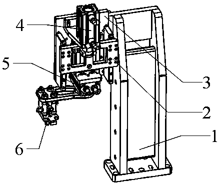
[0013] The present invention will be further described below in conjunction with accompanying drawing.

[0014] The pressure head mechanism includes a support plate 1, a fixed plate 2, a linear guide rail 3, a cylinder module 4, a rotating mechanism 5, and a clamping head 6. It is characterized in that the fixed plate 2 is set on one side of the support plate 1, and the linear guide rail 3 is set On the fixed plate 2, the cylinder module 4 is arranged between the fixed plate 2 and the linear guide rail 3, the cylinder module 4 can slide up and down on the linear guide rail 3, the rotating mechanism 5 is arranged under the cylinder module 4, and the clamping head 6 It is arranged on the output end of the rotating mechanism 5 . Cylinder module 4 is preferably a double-cylinder cylinder. The linear guide 3 is a half-frame type. A plurality of suction nozzles are arranged below the clamping head 6 .

[0015] In actual use, after the workpiece is in place, the present invention ...


PUM


Abstract

The invention relates to a pressure head taking mechanism. The pressure head taking mechanism comprises a supporting plate, a fixed plate, a linear guideway, a cylinder module, a rotating mechanism and a clamping head. During the actual use, after a workpiece is put in place, the pressure head taking mechanism is used for taking or putting a pressure head on a jig. The pressure head is taken or put through the following specific processes: the cylinder module moves downwards along the linear guideway, due to the adoption of the double-cylinder type cylinders, the deviation is very small, even no deviation exists during the up-down movement of the cylinder module, when the clamping head is moved in place, the pressure head is sucked through a suction nozzle, and then is moved to a certain position under the driving of the linear guideway, and the rotating mechanism drives the clamping head to rotate to achieve the taking or putting of the pressure head. The pressure head is taken or put easily through the utilization of the self characteristics of the product and the principle of the cylinders, so that the automatic taking or putting problem of the pressure head is solved, the manual repeated action is avoided, the fastest taking or putting is achieved, the trouble of cumbersome manual operation is overcome, the speed is high, and the efficiency is high.

Description

technical field [0001] The invention relates to the field of mechanical manufacturing, in particular to a pressure head mechanism. Background technique [0002] Electronic technology is an emerging technology developed at the end of the nineteenth century and the beginning of the twentieth century. It developed the fastest and was most widely used in the twentieth century, becoming an important symbol of the development of modern science and technology. [0003] The first generation of electronic products centered on the electron tube. At the end of the 1940s, the first semiconductor triode was born in the world. With the characteristics of small size, light weight, power saving, and long life, it was quickly used by various countries and replaced electronic tubes in a large range. In the late 1950s, the first integrated circuit appeared in the world, which integrated many transistors and other electronic components on a silicon chip, making electronic products more miniatu...

Claims


Application Information

Patent Timeline
Patent Type & Authority Applications(China)
IPC IPC(8): B65G47/91
Inventor 孙丰
Owner SUZHOU SECOTE PRECISION ELECTRONICS CO LTD
Why Eureka
Try Eureka