Emergency braking device of elevator

An emergency braking and elevator technology, which is applied in transportation, packaging, elevators, etc., can solve the problems of increasing the deflection of elastic bodies, increasing the size of elastic bodies, and large-scale emergency braking devices, so as to prevent large-scale Effect

Active Publication Date: 2014-12-24
HITACHI LTD +1
View PDF7 Cites 11 Cited by
  • Summary
  • Abstract
  • Description
  • Claims
  • Application Information

AI Technical Summary

Problems solved by technology

Therefore, in order to reduce the pressing force of the leaf spring, it is necessary to increase the amount of deflection of the elastic

Method used


Image

  • Emergency braking device of elevator
  • Emergency braking device of elevator
  • Emergency braking device of elevator

Examples


Example

[0056] first embodiment

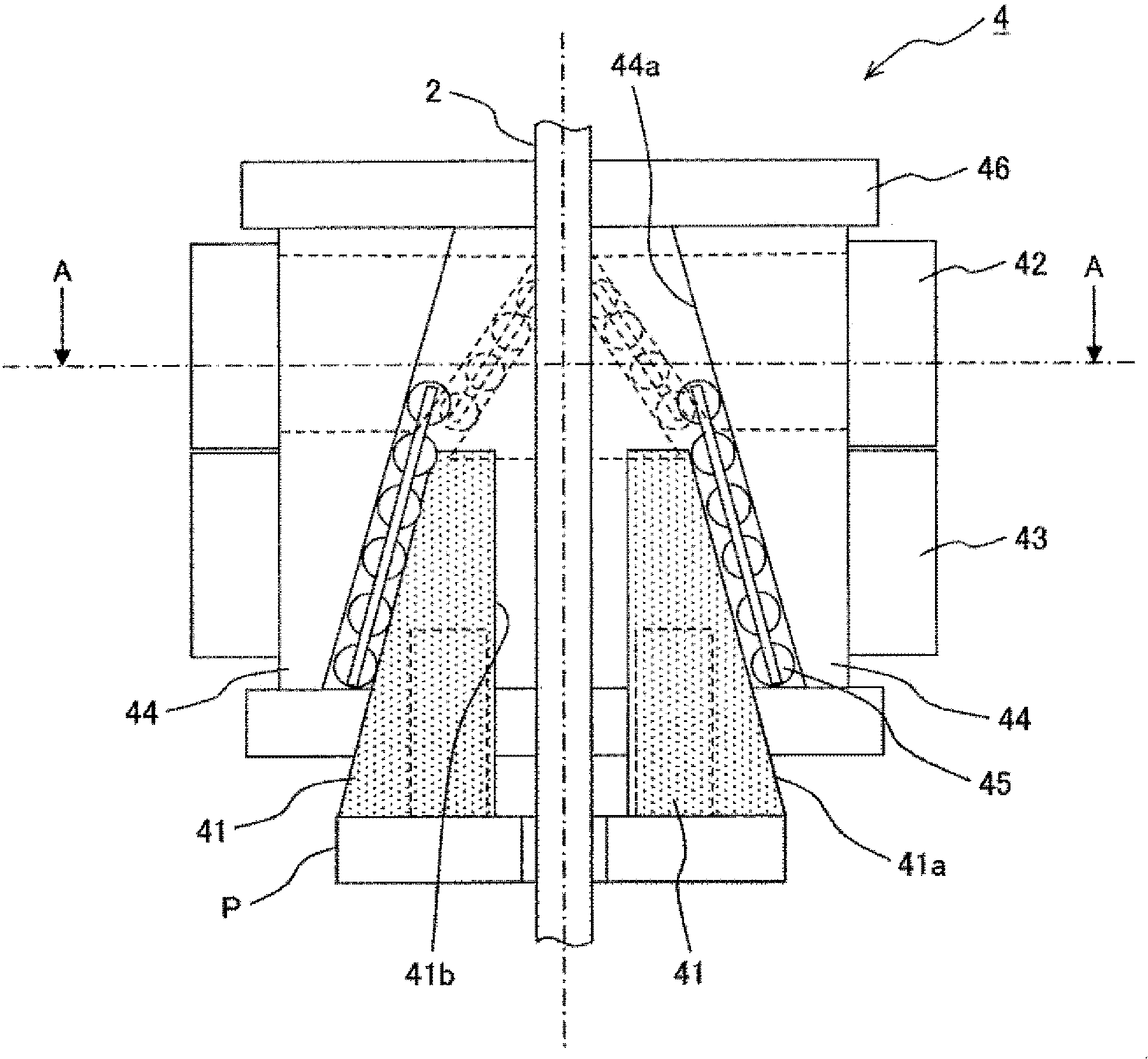
[0057] Below, refer to Figure 3 to Figure 5 The emergency braking device of the first embodiment will be described.

[0058] image 3 It is a schematic diagram showing the emergency braking device for an elevator according to the first embodiment of the present invention. The emergency braking device 4 has: brake shoes 41, which are arranged in pairs on the left and right, and are used to clamp the guide rail 2; When the predetermined speed limit is reached, the brake shoe 41 is brought into sliding contact with the guide rail 2 . In addition, the emergency braking device 4 has an inclined body 44 for guiding the brake shoe 41, a roller 45 provided between the brake shoe 41 and the inclined body 44, and an emergency braking device main body 46 for supporting these components. .

[0059] The brake shoe 41 has a friction surface 41b in contact with the guide rail 2 and an inclined surface 41a provided on the opposite side of the friction surface 4...

Example

[0072] second embodiment

[0073] Figure 11 It is a schematic diagram which shows the emergency brake apparatus of the elevator which concerns on the 2nd Example of this invention. In the first embodiment, the elastic force release device R releases the elastic force of the elastic body by a so-called cam mechanism that moves the inclined body by the brake shoe 41 .

[0074] On the other hand, in the second embodiment, the link mechanism L is employed as the above-mentioned mechanism of the spring force releasing means R. As shown in FIG. After the second slanting body 47 is pressed upward by the locking portion 41c of the brake shoe 41, the third slanting body 48 is opened to the left and right by the link structure L, and the elastic body is opened by opening the third slanting body 48. 42 is opened, thereby releasing the pressure on the brake shoe 41. For the sake of convenience, the second inclined body 47 and the third inclined body 48 have been described using the fo...

Example

[0075] third embodiment

[0076] Figure 12A and Figure 12B It is a schematic diagram which shows the emergency brake apparatus of the elevator which concerns on the 3rd Example of this invention. In the present invention, the pressing force applied to the brake shoe by the divided elastic body as a whole is set so as to provide an appropriate braking force to the emergency braking device under the dynamic friction coefficient acting normally. At this time, the elastic force of the elastic body to be released is determined according to conditions such as braking speed and dynamic friction coefficient, so the division of the elastic body is as follows: Figure 12A and Figure 12B Shown can be divided according to any ratio.


PUM


Abstract

The invention provides an emergency braking device of an elevator, which does not cause large size and furthermore can control a braking force in braking in a range that does not exceed a preset value. The emergency braking device of the elevator presses a braking shoe on a guide rail and make the braking shoe slide on the guide rail for generating a braking force when an elevator cage drops in a speed which exceeds a limited speed. The emergency braking device of the elevator has components of: an upper elastomer and a lower elastomer which applies a pressing force to the guide rail on the braking shoe in braking; an oblique member with an oblique surface which opposes the oblique surface of the braking shoe at the opposite side of the guide rail; rollers which are arranged between the oblique surface of the braking shoe and the oblique surface of the oblique member; and an emergency braking device which supports the components. The emergency braking device of the elevator further comprises the components of: a second oblique member which opens the upper elastomer when the braking force exceeds a preset value, a third oblique member with an oblique surface which opposes the oblique surface of the second oblique member, and rollers which are arranged between the oblique surface of the second oblique member and the oblique surface of the third oblique member.

Description

technical field [0001] The invention relates to an emergency braking device for an elevator. Background technique [0002] As a prior art, in an elevator, when the elevator car descends at a speed exceeding the speed limit due to an accident, in order to safely stop the elevator car at an appropriate deceleration, an emergency brake device is used to brake. The emergency braking device, for example, is configured to clamp the guide rail that guides the elevator car up and down by the brake shoe and the elastic body that are arranged on the elevator car part, and utilize the frictional force generated between the guide rail and the brake shoe to exert pressure on the elevator car. Apply the brakes. [0003] In the prior art, improvements have been made to various problems of the emergency braking device. For example, the frictional force between the guide rail and the brake shoe changes for various reasons, and these changes are immediately apparent as changes in the brakin...

Claims


Application Information

Patent Timeline
IPC IPC(8): B66B5/22
Inventor 座间秀隆远藤广基平野薰佐藤五郎礒谷仁加藤淳志
Owner HITACHI LTD
Why Eureka
Try Eureka